Pogo-Pluggen har jo også en indbygget flash-disk 128-256 Mb, nok til langt de fleste IOT applikationer. I denne blog-post beskriver jeg hvordan jeg installerer Klipper som basis system på den indbyggede flash-disk og derefter installere jeg Klipper til styring af en 3D printer.
På Doozan Forum er der beskrivelser af hvordan man kan installere OpenWRT som et Rescue system på sin Pogo-Plug. Jeg anser min netværks bootede Pogo-Plugs som backup-løsningen, og systemet der er installeret på den interne flash-disk som target i de tilfælde hvor en stand-alone løsning er at foretrække.
OpenWRT på Pogo-Plug er ganske udmærket supporteret, det er blot at finde de relevante bidder, installere dem, og konfigure uBoot til at boote OpenWRT, når først den første OpenWRT er installeret, fungerer den som en hvilket somhelst OpenWRT system, og kan opgraderes via WEB/ssh, hvilket bestemt er noget værd.
- OpenWRT: CloudEngines Pogoplug V2 POGO-E02
- OpenWRT: CloudEngines Pogoplug V4
- Pogoplug Mobile – Potentially the Best OpenWRT Platform @ $10 shipped
- PogoPlug Mobile – Install OpenWrt on internal flash …
- OpenWrt (Lede) on Pogo E02 HowTo
- HowTo: OpenWrt on Kirkwood boxes
- Make and flash a ubifs openwrt into not-supported kirkwood devices
- OpenWRT 24.10.2 kirkwood Downloads
Jeg bruger ikke uBoot-versionen fra OpenWRT, men i stedet Bodhi’s se
OpenWRT på Pogo-Plug, som jeg installerede det
Download
- OpenWRT: cloudengines_pogoplugv4-initramfs-uImage
- OpenWRT: cloudengines_pogoe02-squashfs-sysupgrade.bin
Den første (.uImage), indeholder en openWRT der kan køres alene fra RAM, den skal vi boote, f.ex ved at kopiere den til FAT-usbstick som man så kan boote Pogo-Plug fra.
Med OpenWRT bootet på RAM-disk opgraderes på vanlig vis, via sysupgrade, der vil installere en ny version af OpenWRT på den interne Flash-disk. sysupgrade.bin filen hentes direkte fra OpenWRT med wget.
cd /tmp
wget -O sysupgrade.bin https://downloads.openwrt.org/releases/24.10.2/targets/kirkwood/generic/openwrt-24.10.2-kirkwood-generic-cloudengines_pogoe02-squashfs-sysupgrade.bin
sysupgrade sysupgrade.bin
Også i fremtiden er upgrade processen præcis som andre OpenWRT systemer.
Det enesste som er en lille smule svært er at konfigure uBoot til at boote fra hhv uImage på USB-stick, og OpenWRT instaleret på den interne Flash-Disk.
Nedenfor er output fra fw_printenv
$ fw_printenv
sudo: unable to resolve host pogo1: Name or service not known
addr_fdt=addr=0x700000
addr_uImage=addr=0x800000
addr_uInitrd=addr=0x1100000
addr_zImage=addr=0x800000
arcName=pogo_e02
arcNumber=3542
baudrate=115200
bootcmd=for dev in $default usbfat owrt nfs tftp; do if env exist "${dev}_boot"; then run ${dev}_boot; else run dev_bootz; fi; done; reset
bootdelay=3
console=ttyS0,115200
default=nfs
dev_bootm=run ${dev}_init; run set_bootargs; echo "dev_boot $dev $bootargs"; for blob in uImage uInitrd; do run load_dev_blob; done; bootm $uImage_addr $uInitrd_addr;
dev_bootz=run ${dev}_init; run set_bootargs; echo "dev_boot $dev $bootargs"; for blob in fdt zImage uInitrd; do run load_dev_blob; done; bootz $zImage_addr $uInitrd_addr $fdt_addr;
ethact=egiga0
ethaddr=00:25:31:03:00:00
file_fdt=file=dts/kirkwood-${arcName}.dtb
led_error=orange blinking
led_exit=green off
led_init=green blinking
load_dev_blob=run addr_$blob; if env exists file_$blob; then run file_$blob; else file=$blob; fi; setenv ${blob}_addr $addr; echo "dev=$dev blob=$blob file=$file addr=$addr ${blob}_addr"; run ${dev}_load;
machid=0x831
mtdids=nand0=orion_nand
mtdparts=mtdparts=orion_nand:1M(u-boot),-(ubi)
nc_if=ping $serverip
nc_init=setenv autoload no; dhcp
nc_preboot=run nc_init; setenv nc_ready 0; for pingstat in 1 2 3 4 5; do; sleep 1; if run nc_if; then setenv nc_ready 1; fi; done; if test $nc_ready -eq 1; then run nc_start; fi
nc_start=setenv ncip $serverip; setenv bootdelay 10; setenv stdin nc; setenv stdout nc; setenv stderr nc; version;
nfs_init=setenv autoload no; dhcp; setenv options root=/dev/nfs rootfstype=nfs rootwait nfsroot=$rootpath,v3 ip=$ipaddr:$serverip:$gatewayip:$netmask:$hostname:eth0:off
nfs_load=nfs $addr $rootpath/boot/$file
owrt_boot=run set_bootargs;ubi part ubi; ubi read 0x800000 kernel; bootm 0x800000 $bootargs
partition=nand0,2
set_bootargs=setenv bootargs "console=$console $nc_options $options $mtdparts"
sntp_init=setenv autoload no; dhcp; setenv ntpserverip $serverip; sntp
stderr=serial
stdin=serial
stdout=serial
tftp_init=run nfs_init
tftp_load=tftpboot $addr $serverip:$file
usbfat_boot=run set_bootargs;usb start; fatload usb 0:1 0x800000 uImage; bootm 0x800000
Næste gang installeres Klipper
]]>beskrev jeg hvordan jeg integrerede mine Pogo-Plugs direkte i mit netværk, ved at netværks boote dem fra min fil-server. At udvikle programmer på den diskløs arbejdstation har mange fordele, skulle maskine crache er det blot at reboote da dataene befinder sig sikkert på filserveren.
Men Pogo-Pluggen har jo også en indbygget flash-disk 128-256 Mb, nok til langt de fleste IOT applikationer. I denne blog-post beskriver jeg hvordan jeg installerer Klipper som basis system på den indbyggede flash-disk og derefter installere jeg Klipper til styring af en 3D printer.
På Doozan Forum er der beskrivelser af hvordan man kan installere OpenWRT som et Rescue system på sin Pogo-Plug. Jeg anser min netværks bootede Pogo-Plugs som backup-løsningen, og systemet der er installeret på den interne flash-disk som target i de tilfælde hvor en stand-alone løsning er at foretrække.
OpenWRT på Pogo-Plug
Dette er ganske udmærket supporteret, det er blot at finde de relevante bidder, installere dem, og konfigure uBoot til at boote OpenWRT, når først den første OpenWRT er installeret, fungerer den som en hvilket somhelst OpenWRT system, og kan opgraderes via WEB/ssh, hvilket bestemt er noget værd.
- OpenWRT: CloudEngines Pogoplug V2 POGO-E02
- OpenWRT: CloudEngines Pogoplug V4
- Pogoplug Mobile – Potentially the Best OpenWRT Platform @ $10 shipped
- PogoPlug Mobile – Install OpenWrt on internal flash …
- OpenWrt (Lede) on Pogo E02 HowTo
- HowTo: OpenWrt on Kirkwood boxes
- Make and flash a ubifs openwrt into not-supported kirkwood devices
- OpenWRT 24.10.2 kirkwood Downloads
Jeg bruger ikke uBoot-versionen fra OpenWRT, men i stedet Bodhi’s se
KlipperWRT på Pogo-Plug
Klipper installeret på Pogo-Plug der kører OpenWRT. Jer er ikke stødt på denne komibation, men der er KlipperWRT installationer på anden hardware, så det burde også være muligt. Her er lidt inspiration:
- Upgrading the Creality Sermoon V1 3D printer
- GitHub: shivajiva/KlipperWrt on Creality Wi-Fi Box
- GitHub: mick-wloch/KlipperWRT on GL.iNet GL-MT300N
Klipper under Debian på Pogo-Plug på Diskløs Filsystem
Jeg har allerede Klipper kørende i drift på en Intel Ubuntu PC, så det burde være ligetil at installere et tilsvarende system under Debian. Grunden til at jeg ikke gør det, er at jeg tit har 3D-prints der tager døgn, og for at minimere chancerne for at det går galt vil jeg minimere antal af systemer det baserer sig på. Det vil være træls at 3D-prints fejler fordi nettet fejler (eller serveren løber tør for bits) eller en anden grund som ikke har noget som helst med 3D-printet at gøre.
- Debian 12 and Klipper – General Discussion
- GitHub: Phil1988/FreeQIDI A tutorial to make a clean and recent armbian-klipper system
- GitHub: dw-0/kiauh: Klipper Installation And Update Helper
Klipper under Debian på Pogo-Plug på local disk
Dette er endnu en mulihed, enten på en USB-stick, en SATA-flashdisk, eller den interne flash-disk.
Det var mest betragtninger og links/bookmarks nu skal bare beslutte mig.
Næste gang installeres OpenWRT på Pogo-Plug
]]>- Dual Applications on ATmega2560 – Marlin AND Klipper – FAIL (well almost)
- AVR DualBoot Bootloader
- Install Klipper on your old 3D-Printer and still keep Marlin
It seems many printers are moving to Klipper these days, and mine probably should too. But I am very satisfied with the Marlin software that controls my printer, as of 2023 you have to install new firmware on your Microcontroller to run Klipper – well now it’s 2024 and I want it all – all the time.
With Marlin the full program is flashed onto the CPU, meaning that if you want to implement new features you need to install new firmware on the printer. Klipper on the other hand has the high-level part of the program running under Linux, hence new features can be implemented by editing some config files or adding some Python code. Hence it is clear that the development of new features will be much easier with Klipper than with Marlin. One small example that comes to my mind is adaptive printer-bed-leveling, where you only map the Z-position of the part of the print-bed that will hold a print.
I like my 3D printers as they are, especially the workflow where I put a print file on an SD-card, put it in the printer, and print it, but I am still curious, will Klipper make a difference for me, so I would like to try it out.
This was my incentive for implementing Dual-Boot capability on the ATmega2560, which I have described in my 2 previous blog posts
The primary application which would be Marlin, it could be the firmware currently controlling your 3D-printer, it needs no modification, it might even be the original firmware.
The secondary application which would be Klipper, will need to be relocated to a free address space after the Marlin Firmware, and the Klipper firmware needs to be modified to run there, and this is the real topic of this blog post.
Compile Klipper so that it will run in the upper address space
and redirect read of data/code in Flash there
In the previous blog post, we got Klipper running in as a secondary firmware, but we had to shrink Marlin so it all would fit in the lower 128 kbyte Flash. The dualtool.sh from the previous post gives us this info
 dualtool klipper/out/klipper.elf
# This Device is runing DualBoot based on optiboot 8.3
# klipper/out/klipper.elf do not have  trampolines
# NAME[1]=klipper BASE[1]=0x17000 SIZE[1]=32244
 0x00000 - 0x17000 1st flashed with marlin DEFAULT
 0x17000 - 0x3fb00 2nd ../build.klipper/ramps_2nd/klipper.elf 32244 bytes
 0x3fb00 - 0x3fc00 irq vector table... 256 bytes
 0x3fc00 - 0x40000 DualBoot bootloader 1024 bytes
# Keep primary firmware, not erasing
# Replace secondary firmware,
no trampolines in secondary firmware
 DUAL_BASE max 0x37d0c -> 0x37d00
This time Klipper will be relocated higher to give Marlin more space (the base could be up to 0x37d00), we will choose 0x34000. The relocation is handled during the linking stage, by adding these arguments, to the final call to avr-gcc
EXTRA_LDFLAGS="-mrelax -fno-jump-tables -Wl,--section-start=.text=0x34000"
Now Klipper will be able to run in the newly assigned address space, but all its read-only data/strings are stored in Flash, this will be accessed via 16-bit pointers and Klipper will just get hold of some random code from the Marlin-code instead of date from its own address space. That was the reason we had to have both Marlin and Klipper fit in the lower 128k Flash in the previous blog post.
To find out where Klipper does these calls the source code is scanned for calls to
- pgm_read_*() functions, which only happens in klipper/src/avr/pgm.h
- *_P() functions which only happens in klipper/src/command.c
Luckily for us, the code is well written and there are only two places to understand and modify, and the fix is trivial too
READP(variable) macro
except for one call to memcpy_P() all access to read-only variables goes through this macro
  #define READP(VAR) ({                                                   \
    _Pragma("GCC diagnostic push");                                     \
    _Pragma("GCC diagnostic ignored \"-Wint-to-pointer-cast\"");        \
    typeof(VAR) __val =                                                 \
        __builtin_choose_expr(sizeof(VAR) == 1,                         \
            (typeof(VAR))pgm_read_byte(&(VAR)),                         \
        __builtin_choose_expr(sizeof(VAR) == 2,                         \
            (typeof(VAR))pgm_read_word(&(VAR)),                         \
        __builtin_choose_expr(sizeof(VAR) == 4,                         \
            (typeof(VAR))pgm_read_dword(&(VAR)),                        \
        __force_link_error__unknown_type)));                            \
    _Pragma("GCC diagnostic pop");                                      \
    __val;                                                              \
    })
This makes the Klipper source code easier to maintain since there is only one function READP() which does the heavy lifting, and has to be adapted to the underlying MCU, this is also very good for us since we just need to replace this with a version that gets hold of the flash-content from the 16-bit address space we are operating in.
  #define READP(VAR) ({                                                   \
    _Pragma("GCC diagnostic push");                                     \
    _Pragma("GCC diagnostic ignored \"-Wint-to-pointer-cast\"");        \
    typeof(VAR) __val =                                                 \
        __builtin_choose_expr(sizeof(VAR) == 1,                         \
            (typeof(VAR))pgm_read_byte_here(&(VAR)),                         \
        __builtin_choose_expr(sizeof(VAR) == 2,                         \
            (typeof(VAR))pgm_read_word_here(&(VAR)),                         \
        __builtin_choose_expr(sizeof(VAR) == 4,                         \
            (typeof(VAR))pgm_read_dword_here(&(VAR)),                        \
        __force_link_error__unknown_type)));                            \
    _Pragma("GCC diagnostic pop");                                      \
    __val;                                                              \
    })
Now we just have to implement the pgm_read_????_here() functions. The pcm_read_????() function is defined in avr/pgmspace.h and they end up using the LPM instruction to get hold of the flash content, we just need to change that to use the ELPM instruction which adds the RAMPZ to the pointer to be able to access all the Flash on the device
#define __hereLPM_classic__(addr)   \
(__extension__({                \
    uint16_t __addr16 = (uint16_t)(addr); \
    uint8_t __result;           \
    __asm__ __volatile__        \
    (                           \
        "elpm" "\n\t"            \
        "mov %0, r0" "\n\t"     \
        : "=r" (__result)       \
        : "z" (__addr16)        \
        : "r0"                  \
    );                          \
    __result;                   \
}))

#define __hereLPM_word_classic__(addr)          \
(__extension__({                            \
    uint16_t __addr16 = (uint16_t)(addr);   \
    uint16_t __result;                      \
    __asm__ __volatile__                    \
    (                                       \
        "elpm"           "\n\t"              \
        "mov %A0, r0"   "\n\t"              \
        "adiw r30, 1"   "\n\t"              \
        "elpm"           "\n\t"              \
        "mov %B0, r0"   "\n\t"              \
        : "=r" (__result), "=z" (__addr16)  \
        : "1" (__addr16)                    \
        : "r0"                              \
    );                                      \
    __result;                               \
}))
#define __hereLPM_dword_classic__(addr)         \
(__extension__({                            \
    uint16_t __addr16 = (uint16_t)(addr);   \
    uint32_t __result;                      \
    __asm__ __volatile__                    \
    (                                       \
        "elpm"           "\n\t"              \
        "mov %A0, r0"   "\n\t"              \
        "adiw r30, 1"   "\n\t"              \
        "elpm"           "\n\t"              \
        "mov %B0, r0"   "\n\t"              \
        "adiw r30, 1"   "\n\t"              \
        "elpm"           "\n\t"              \
        "mov %C0, r0"   "\n\t"              \
        "adiw r30, 1"   "\n\t"              \
        "elpm"           "\n\t"              \
        "mov %D0, r0"   "\n\t"              \
        : "=r" (__result), "=z" (__addr16)  \
        : "1" (__addr16)                    \
        : "r0"                              \
    );                                      \
    __result;                               \
}))


#define pgm_read_byte_here(address_short) __hereLPM_classic__((uint16_t)(address_short))
#define pgm_read_word_here(address_short) __hereLPM_word_classic__((uint16_t)(address_short))
#define pgm_read_dword_here(address_short) __hereLPM_dword_classic__((uint16_t)(address_short))
memcpy_P()
There is one call to memcpy_P(). Instead of reimplementing a version that works on the current 16-bit address space, it is easier to just replace memcpy_P() with a for-loop using the READP() macro from above, here are the changes needed to do that:
diff --git a/src/command.c b/src/command.c
index 39c09458..ed4dc85b 100644
--- a/src/command.c
+++ b/src/command.c
@@ -156,7 +156,13 @@ command_encodef(uint8_t *buf, const struct command_encoder *ce, va_list args)
             *p++ = v;
             uint8_t *s = va_arg(args, uint8_t*);
             if (t == PT_progmem_buffer)
+#ifdef DUALBOOT_BASE
+               for (uint16_t i=0; i<v; i++) {
+                    p[i] = READP( s[i] );
+               }
+#else
                 memcpy_P(p, s, v);
+#endif
             else
                 memcpy(p, s, v);
             p += v;

</pre
Initialization of RAMPZ
This is done by adding a few lines to the initialization of the program, here are the diffs
diff --git a/src/avr/main.c b/src/avr/main.c
index 0523af41..988d2982 100644
--- a/src/avr/main.c
+++ b/src/avr/main.c
@@ -14,6 +14,16 @@

 DECL_CONSTANT_STR("MCU", CONFIG_MCU);

+#ifdef DUALBOOT_BASE
+static void
+__attribute__((section(".init3"),naked,used,no_instrument_function))
+init3_set_eind (void)
+{
+  __asm volatile ("ldi r24,pm_hh8(__vectors)\n\t"
+                  "out %i0,r24" :: "n" (&RAMPZ) : "r24","memory");
+  __asm volatile ("out %i0,r24" :: "n" (&EIND) : "r24","memory");      // not needed
+}
+#endif

 /****************************************************************
  * Dynamic memory
Thats it – The source code is available:
GitHub.com/StorePeter/DualFirmware_Marlin_Klipper
The README.md will guide you through the process.
Best Regards
StorePeter
]]>- Dual Applications on ATmega2560 – Marlin AND Klipper – FAIL (well almost)
- AVR DualBoot Bootloader
- Install Klipper on your old 3D-Printer and still keep Marlin
In the first post in this series, I described how I wanted to have my 3D-printer be able to run Marlin firmware and the Klipper firmware without having to reflash a new firmware to the ATmega2560.
The idea was to relocate the secondary firmware to the upper half of the Flash. The Bootloader would set IVSEL before passing control to the secondary firmware, and the bootloader interrupt vector table would call the corresponding interrupt routines in the secondary firmware. This worked great for the test program I had written that did not use trampolines, but neither Klipper nor Marlin would run in the upper address space when relocated there. So even though my concept for DualBoot firmware on an ATmega2560 worked as expected in reality it was a FAIL, but there is a
Solution:
Compile the secondary firmware so that it does not rely on trampolines,
redirect read of data/code in flash to the upper address space
or simply avoid using flash above 128kbyte
The ATmega2560 is an 8-bit micro-processor working in a 16-bit address space (Harward architecture), but this processor has 256 kbyte of FLASH. Most address-related machine instructions are done in 16-bit, and it is more efficient to jump to an address in the lower range than jumping to an upper address. avr-gcc takes advantage of this and implements a trampoline area just above the interrupt vectors with jumps that will send you to code in the upper address space when you call the trampoline.
Trampolines are only needed if there is a call to some code in a different 16-bit bank, For smaller programs, like my test programs. The linker can be directed to avoid jump-tables,
Klipper is a fairly small (32kbyte flash) hence this point of the problem can be solved for Klipper.
Marlin can be larger than 128kbyte so this does not apply to Marlin, Marlin still needs to have its trampoline area in the lower address space.
So there is light at the end of the tunnel, as long as we have Marlin as the primary firmware, and can figure out how to relocate Klipper to the upper address space.
Flash is not only used for storing the program, read-only variables/tables/text-strings are often saved in FLASH since there is limited RAM. As this is a Harward CPU routines like pgm_read_byte( 16bit pointer) is used to read them. When the secondary firmware is relocated to the upper address space, the read of Flash-content will still return data from the lower flash, unless pgm_read_byte_far(32-bit address) is used. The good news is that we probably only need to patch the implementation of pgm_read_byte(16-bit address) on the secondary firmware to get around this.
The AVR DualBoot bootloader I presented in the previous blog post works as expected, we just need to make sure the secondary firmware is patched and compiled in a way so that trampolines are avoided and flash-reads are directed to the right area.
The AVR program counter and thereby address is 16-bit but this addresses words, hence the normal limit is 128 kbyte.
DualBoot:
As long as you stay below 128k,
relocation is the only modification needed for the secondary firmware
the primary firmware need no changes
For now, I will continue using only the lower 128k flash area.
A stripped-down Marlin (no sd-card support) as primary firmware, and Klipper as secondary firmware is compiled, so they can fit within the lower 128k flash.
avr-size ../build.marlin/ramps/firmware.elf ../build.klipper/ramps_2nd/klipper.elf
text data bss dec hex filename
89846 208 2696 92750 16a4e ../build.marlin/ramps/firmware.elf
32202 42 366 32610 7f62 ../build.klipper/ramps_2nd/klipper.elf
Success – Marlin @ 0x0000 – Klipper @ 0x16000
To test this out a version of the DualBoot code presented in my previous posting was made, this time the secondary firmware would be assumed to start at 0x16000. A stripped-down but otherwise unmodified version of Marlin was flashed to 0x0000, and Klipper was relocated to 0x16000 and flashed there, which worked as expected. HURRAH we now have a working – For the first time in world history a 3D printer is running Marlin and Klipper on the same firmware.
DualBoot with secondary firmware on a fixed base address
DualBoot has the load address for the secondary firmware hardcoded into the bootloader, which means that if you want to install a larger primary firmware you have to modify and flash a new bootloader, which again would mean that you would have to have physical access to the mainboard, and connect f.ex an USBasp for this, pretty inconvenient. More able people than me might be able to have the bootloader modify itself, but even if that would be possible, I prefer to have the bootloader untouched, it should after all be our backup plan. But there is an easy fix for this
DualBoot with secondary firmware dynamic base address
The problem is that the interrupt table in the bootloader has to forward the interrupt calls to the secondary firmware, so the bootloader needs to know where to jump to, this is hardcoded into the bootloader.
The interrupt vector table in the secondary firmware is itself an array of 4-byte assembly codes that call the relevant interrupt routine. Hence we can have our cake and eat if we:
- Copy the interrupt table from the secondary firmware to a fixed location just below the DualBoot bootloader.
- Let the DualBoot firmware interrupt table always call the entries just below the bootloader, this would even work with the reset address.
Hence no changes to the DualBoot bootloader presented in the previous post are necessary, just compile a version of DualBoot that expects the interrupt-table to be just below the bootloader.
dualtool.sh
I have written a small tool, to check whether the trampolines are located, in the lower 16-bit address area. dualtool.sh also checks bounds and copies the interrupt vector table to the area just below the bootloader, finally, the name of the files and the base address for the secondary firmware are saved there too.
Usage: dualtool.sh [option] [primary_firmware.elf] [secondary_firmware.elf]
           prints current firmware-map
    file.elf       firmware (primary and/or secondary) to load
    file.hex       primary firmware can be in hex format
    -w             program device with given .elf fiiles
    -e             erase device
    -E eeprom.hex  program EEPROM
    -c usbasp      use usbasp as ISP
    -b baud
    -p mcu
    -v             verbose
check for trampolines,handle vector_table, suggest DUAL_BASE
Below is the output of such a check, it uses Avrdude to access the flash in the microprocessor.
# MCU=atmega2560 FLASH=262144 VECT_BASE=0x3fb00 VECT_SZ=256 BOOT_BASE=0x3fc00 BOOT_SZ=1024
# This Device is runing DualBoot based on optiboot 8.3
# NAME[0]=marlin BASE[0]=0x00000 SIZE[0]=90054
# TRAMPOLINES_START[0]=0x000001b2
# TRAMPOLINES_END[0]=0x00000322
# ../build.klipper/ramps_2nd/klipper.elf do not have trampolines
# NAME[1]=klipper BASE[1]=0x16000 SIZE[1]=32244
0x00000 - 0x16000 1st ../build.marlin/ramps/firmware.elf 90054 bytes DEFAULT
0x16000 - 0x3fb00 2nd ../build.klipper/ramps_2nd/klipper.elf 32244 bytes
0x3fb00 - 0x3fc00 irq vector table... 256 bytes
0x3fc00 - 0x40000 DualBoot bootloader 1024 bytes
# Replace primary firmware,
DUAL_BASE min 0x15fc6 -> 0x16000
# Replace secondary firmware,
no trampolines in secondary firmware
DUAL_BASE max 0x37d0c -> 0x37d00
dualtool.sh can also flash firmware to the chip when given the -w option
dualtool.sh ../build.marlin/ramps/firmware.elf ../build.klipper/ramps_2nd/klipper.elf
That was it, my 3D printer can now run Klipper when connected to Linux computer, but still works in standalone mode under Marlin, all it takes is the flip of a switch.
The main limitation is that half the flash is not usable, but Marlin without SD-card support is removing one of the features I like about Marlin.
The Klipper firmware is much smaller than Marlin. In my next blog post, I will describe what it takes to make the Klipper firmware run flawlessly from the upper address space. Allowing us to have a full versio of Marlin running as primary firmware.
This means that in most cases we can keep our old trusted Marlin already installed on the printer, and just install Klipper alongside it. Hence we try out Klipper without burning any bridges. Just as I had envisioned from the beginning, it was probably a little more complicated than I had thought.
The source code for avr-dualboot bootloader and tool is available on:
https://github.com/StorePeter/avr-dualboot
In the last blog-post we will make Klipper run in the upper address space
Install Klipper on your old 3D-Printer and still keep Marlin
]]>This is part 1 in a series of 3 blog-posts describing how I make Marlin and Klipper coexist on my 3-Printers:
- Dual Applications on ATmega2560 – Marlin AND Klipper – FAIL (well almost)
- AVR DualBoot Bootloader
- Install Klipper on your old 3D-Printer and still keep Marlin
I have been using Marlin on my 3D printers for the last 6 years, it is convenient just to be able to copy the gcode to an SD-card, install it, and press print. The only thing that bothers me is that it is so slow to copy things to the SD-card via USB, so you are kind of forced to do it this way.
It seems a lot of printers are moving to Klipper these days, and mine probably should too, this would make network access so much better, but I will lose the simplicity of just being able to print from an SD-card. And you are burning all your bridges, the Marlin firmware on the printer will be overwritten with Klipper.
Wouldn’t it be nice if you could use both Marlin and Klipper on the same 3D-printer, Normally the printer would just run Marlin, but if it received a Klipper directions it would reboot into Klipper.
For this first version, we will settle for a physical switch which depending on the position would boot the printer in either Marlin or Klipper. In this way, we do not need to make any changes to Marlin.
On an Arduino, we normally do have two functionalities in the firmware at the same time, namely the bootloader optiboot and the application sketch we are working on.
On the Atmega reset/interrupt vectors reside at address 0x0000, but if the IVSEL bit in the MCUCR register is set the reset/interrupt vector table will start at the Boot-Loader-base-address, in case of a 1k bootloader 0x3fc00.
Optiboot is not using interrupts, but we can add an interrupt vector table whose function solely is to call the relevant interrupt routine in application number 2
The following memory layout will be chosen
- Primary Application (Marlin) 128k , 0 – 128k
- Secondary Application (Klipper) 127k, 128k – 255k
- Bootloader (modified version ofOptiboot), 1k 255k – 256k
The primary application (which would be Marlin) would not need any modification, but the max size has been decreased t0 128k
The secondary application (which would be Klipper) would need to be relocated to 0x20000, which can be done by adding an extra line to the Klipper Makefile.
Optiboot needs an interrupt table where all the entries just jumps to the interrupt routines provided by the secondary application, and on startup depending on the state of DUALBOOT_BIT either jump to 0x0000 and we will be running the primary application, or set IVSEL and jump to 0x20000 and we will be running the secondary application.
That is all there is to it, (In Denmark we say: Hvor svært kan det være). I wonder why nobody has implemented something like this before, it seems to be straightforward to implement. And I can see other uses where it would be nice to have an alternative firmware available.
Proof of Concept
As I said very few changes are needed to the bootloader, download the sources from GitHub, the changes to Optiboot are trivial as shown below.
diff --git a/optiboot/bootloaders/optiboot/optiboot.c b/optiboot/bootloaders/optiboot/optiboot.c
index 6d9e0cc..3a83565 100644
--- a/optiboot/bootloaders/optiboot/optiboot.c
+++ b/optiboot/bootloaders/optiboot/optiboot.c
@@ -702,6 +702,65 @@ void pre_main(void) {
 #endif
     "1:\n"
     );
+#ifdef DUALBOOT
+    asm("   jmp (%0+4)\n"
+        "   jmp (%0+8)\n"
+        "   jmp (%0+0xc)\n"
... Lines removed, but I am sure you figured this out ...
+        "   jmp (%0+0xdc)\n"
+        "   jmp (%0+0xe0)\n"
+        ::"i"((uint32_t)DUALBOOT_BASE));
+#endif
 }


@@ -821,6 +880,15 @@ int main(void) {
       watchdogConfig(WATCHDOG_OFF);
       // Note that appstart_vec is defined so that this works with either
       // real or virtual boot partitions.
+#ifdef DUALBOOT
+       MCUCR = 1<<IVCE;                // enable interrupt vectors change
+       if ((DUALBOOT_PIN && (1<<DUALBOOT_BIT)) == 0) {
+               MCUCR = 1<<IVSEL;       // move interrupt vectors to bootloader
+               asm("  jmp 0x3000\n"::);
+       }
+       MCUCR = 0;                      // interrupt vectors at 0
+#endif
       __asm__ __volatile__ (
         // Jump to 'save' or RST vector
 #ifdef VIRTUAL_BOOT_PARTITION
To compile and flash this to the atmega250 I use an USBasp. I have created my own Makefile which just uses the Makefile in Optiboot, here are the relevant lines from my Makefile
MCU.    = atmega2560
AVRDUDE = avrdude
TTY     = $(wildcard /dev/serial/by-id/usb-*)
DEVICE  = atmega2560
ISP     = $(AVRDUDE) -c arduino -P $(TTY) -b 115200 -p $(DEVICE)
DUAL_DEFS      += -DDUALBOOT=$(DUAL_BASE) -DDUALBOOT_PORT=$(DUAL_PORT) -DDUALBOOT_BIT=$(DUAL_BIT)
OPTIBOOT_DIR   := optiboot/optiboot/bootloaders/optiboot
OPTIBOOT_FLAGS += UART=0 BIGBOOT=1
OPTIBOOT_FLAGS += LED=B7 LED_START_FLASHES=3
OPTIBOOT_FLAGS += ISPTOOL=usbasp ISPPORT= ISPSPEED= LOCKFUSE=FF
OPTIBOOT_DUAL  += DEFS="$(DUAL_DEFS)" CUSTOM_VERSION=100
OPTIBOOT_SRC   := $(OPTIBOOT_DIR)/optiboot.c
OPTIBOOT_ELF   := $(OPTIBOOT_DIR)/optiboot_$(MCU).elf

# .elf   -> make $(MCU) compiles to .elf
# .flash -> make $(MCU)_isp will flash bootloader to device too
# optiboot -> no changes
# dualboot -> adds interript vector table and dualboot capability
optiboot.flash optiboot.elf dualboot.flash dualboot.elf: $(OPTIBOOT_SRC) Makefile
        make -C $(OPTIBOOT_DIR) $(OPTIBOOT_FLAGS) \
                $(if $(filter dualboot.%,$@), $(OPTIBOOT_DUAL)) \
                clean \
                $(MCU)$(if $(filter %.flash,$@),_isp)
        cp $(OPTIBOOT_ELF) $(@:flash=elf)
        $(if $(filter %.flash,$@), mkdir -p  $(FIRMWARE_DIR); cp $(@:flash=elf) $(FIRMWARE_DIR))
To prove the concept I just wrote a tiny application that does interrupt-driven UART communication. The source is below, all the watchdog circus is not necessary but at one point I believed the Watchdog timer was causing me trouble.
#include <avr/pgmspace.h>
#include <avr/wdt.h>
#include <util/delay.h>
#include <stdio.h>

// for atmega2560
#define BOOTLOADEREND 0x3ffff

#define STR_HELPER(s) #s
#define STR(s) STR_HELPER(s)
// IO-pin is referenced as Port,Bit f.ex arduino pin13 is B,7
// hence we only only need one define per pin passed from the Makefile
//, where optiboot uses separate defines for port and bit
// _... macroes unravels the setting needed
// G_... is only used by the _... macroes
#define G_REG(reg,port,bit)	reg ## port
#define G_BIT(port,bit)		bit
#define G_MASK(port,bit)	(1<<bit)
#define G_STR(port,bit)		STR(port) "," STR(bit)
#define _PORT(...)	G_REG(PORT,__VA_ARGS__)
#define _DDR(...)	G_REG(DDR,__VA_ARGS__)
#define _PIN(...)	G_REG(PIN,__VA_ARGS__)
#define _BIT(...)	G_BIT(__VA_ARGS__)
#define _MASK(...)	G_MASK(__VA_ARGS__)
#define _STR(...)	G_STR(__VA_ARGS__)

char volatile *cpt;

ISR(USART0_UDRE_vect)
{
	char c = *cpt++;
	if (*cpt == 0) {			// c was the last char in buffer
		UCSR0B &= ~(1 << UDRIE0); // disable UDRE interrupt } UDR0 = c; } void uart_init() { uint16_t baud_setting = (F_CPU / 4 / BAUD - 1) / 2; if (baud_setting > 4095) {
		UCSR0A = 0;
		baud_setting = (F_CPU / 8 / BAUD - 1) / 2;
	} else {
		UCSR0A = 1 << U2X0; } UBRR0H = baud_setting >> 8;
	UBRR0L = baud_setting;
	UCSR0B = 1 << TXEN0;
}

void puts_polled(char *str)
{
	while (*str) {
		while (!(UCSR0A & (1 << UDRE0))) ;	// wait for UDR0 empty
		UDR0 = *str++;
	}
}

void puts_irq(char *str)
{
	cpt = str;
	UCSR0B |= (1 << UDRIE0);		// enable UDRE interrupt
	while (UCSR0B & (1 << UDRIE0)) ; // bit will be cleared by final char interrupt } char watchdog_count = 0; volatile char sleeping; ISR(WDT_vect) { sleeping = 0; watchdog_count++; puts_polled(" Bow Wow\r\n"); } void cause_of_reset() { puts_polled("\r\n-> ");
	if (MCUSR & (1 << WDRF)) {
		watchdog_count++;
		puts_polled("Watchdog");
	}
	if (MCUSR & (1 << BORF)) {
		puts_polled("Brownout");
	}
	if (MCUSR & (1 << EXTRF)) {
		puts_polled("External");
	}
	if (MCUSR & (1 << PORF)) {
		puts_polled("Power On");
	}
	puts_polled(" Reset\r\n");
	MCUSR = 0;
}

int main(void)
{
	char buffer[100];

	uart_init();
	cause_of_reset();
	puts_polled(STR(NAME) " hello polled print, base:" STR(BASE));

	wdt_enable(WDTO_2S);
	sei();

	_DDR(DUALBOOT_PORT_BIT) &= ~_MASK(DUALBOOT_PORT_BIT);	// 50 k internal pullup
	_PORT(DUALBOOT_PORT_BIT) |= _MASK(DUALBOOT_PORT_BIT);
	while (1) {
		wdt_reset();

		puts_irq(STR(NAME) " hello IRQ print, base: " STR(BASE));
		sprintf(buffer, ", Port,Bit: " _STR(DUALBOOT_PORT_BIT) " = %s, watchdog_count=%d\r\n",
			(_PIN(DUALBOOT_PORT_BIT) & _MASK(DUALBOOT_PORT_BIT)) ? "high" : "low",
			 watchdog_count);
		puts_irq(buffer);
		if (watchdog_count==1) {
			puts_irq("Enable Watchdog IRQ, set WDTCSR = 1<<WDIE, next expect Barking\r\n");
			WDTCSR = 1 << WDIE;	// enable watchdo interrupts
		}
		puts_irq("sleep - watchdog is set to 2 sec\r\n");
		sleeping = 1;
		while (sleeping);
		puts_irq("Survived Watchdog\r\n");// WDTCSR.WDIE must be set to enable watchdog interrupt
	}
}
Both primary.elf and secondary.elf are compiled from the same source, below are the relevant lines from the Makefile
LDFLAGS += -Wl,--section-start=.text=0x20000

primary.elf: hello.c
        $(CC) -DNAME=$(@:.elf=) -DBASE=0 $(CFLAGS) -o $@ $<

secondary.elf: hello.c
        $(CC) -DNAME=$(@:.elf=) -DBASE=0x20000 $(CFLAGS) $(LDFLAGS) -o $@ $<

%.hex: %elf
	avr-objcopy  -j .text -j .data -O ihex $< $@

flash: primary.hex secondary.hex
	$(ISP) -U flash:w:primary.hex:i -U flash:w:secondary.hex:i
To flash both firmware to the atmega2560. Avrdude is used to program it via the newly installed dualboot version of the optiboot bootloader on the atmega2560, the USBasp was only used for flashing the bootloader.
Success – but Klipper FAILING as the secondary application
So it is testing time, to see what is going on the serial port I am just using
picocom -l /dev/serial/by-id/usb-* -b 115200
below is the output from my hello.c program
-> External Reset
primary hello polled print, base:0
primary hello IRQ print, base: 0, Port,Bit: G,0 = high, watchdog_count=0
sleep - watchdog is set to 2 sec

-> Watchdog Reset
primary hello polled print, base:0
primary hello IRQ print, base: 0, Port,Bit: G,0 = high, watchdog_count=1
Enable Watchdog IRQ, set WDTCSR = 1<<WDIE, next expect Barking
sleep - watchdog is set to 2 sec
 Bow Wow
Survived Watchdog
primary hello IRQ print, base: 0, Port,Bit: G,0 = high, watchdog_count=2
sleep - watchdog is set to 2 sec

-> Watchdog Reset
....
Now we will pull pin G,0 down to ground and try again and we will see
-> External Reset
secondary hello polled print, base:0x20000
secondary hello IRQ print, base: 0x20000, Port,Bit: G,0 = low, watchdog_count=0
sleep - watchdog is set to 2 sec

-> Watchdog Reset
secondary hello polled print, base:0x20000
secondary hello IRQ print, base: 0x20000, Port,Bit: G,0 = low, watchdog_count=1
Enable Watchdog IRQ, set WDTCSR = 1<<WDIE, next expect Barking
sleep - watchdog is set to 2 sec
 Bow Wow
Survived Watchdog
secondary hello IRQ print, base: 0x9000, Port,Bit: G,0 = low, watchdog_count=2
sleep - watchdog is set to 2 sec

-> Watchdog Reset
Everything works as expected, now it is time to try some real applications,
- Marlin is compiled with out any changes
- Klipper need the addition of –section-start directive to instruct the linker to relocate klipper to the upper address space.
- flash as before
Marlin works fine, but Klipper FAIL. hmm, the next thing to try is of course:
- Klipper compiled out of the box without any changes
- Marlin relocated to 0x20000
- flash as before
This time Klipper works as expected, but Marlin FAIL.
So we FAILED on our initial goal but also proved that dual applications are indeed possible.
- What is wrong with Klipper or Marlin why will they not run in the upper address space, or
- Are more changes needed to Optiboot to make this work?
The seasoned hacker has probably figured out what is wrong by now, a little hint might be that the atmega2560 is an 8-bit micro-processor working in a 16-bit address space (Harward architecture), but the processor we are using has 256 kbyte of FLASH memory (18bit)
So there might be good reasons why nobody has implemented a dualboot-bootloader on AVR before ;-(
I am not giving up, and I will succeed, you can follow my quest here:
]]>Tarantulaen var faktisk nogenlunde god nok, jeg lavede en del små-forbedringer, men blev aldrig færdig med at designe og bygge min egen 3D printer, Tarantulaen var som sagt nogenlunde god nok, selv med en 8 bit CPU.
Over årene er der er blevet printet masser af små kasser, beslag og reservedele til ting der er gået i stykker eller blevet væk, f.ex den der lille tingest for enden af ostehøvlen
En nogenlunde virkende 3D-printer på bordet, er bedre end 10 fantastiske designs på taget.
3D-printing er ikke rocket science og hvis man ellers kan leve med en langsom print-tid, så kan selv de mest flimsy 3D-printerer lave nogenlunde gode prints, med den rigtige tuning kan man lave endog særdeles fine prints.
Men det er langsomt, og tuning tager tid.
For seks år siden kunne det sikkert betale sig at bygge sin egen printer, Det fornuftige ville have været at klone f.ex. en Prusa printer (den er open source) og lade være med at fifle med egne fantastiske ideer, men det er der jo ingen sjov ved.
Skal man have en 3D-printer nu til dags, har man efter min mening flere gode muligheder:
- €1,199 – Original Prusa MK4 3D Printer – Stadig noget af det bedste du kan få.
- €489 – Original Prusa MINI+ Semi-assembled 3D Printer – Lidt mindre, men lige så god.
- €250 – Creality Ender 3 – Den mest solgte printer, der fås i et utal af configurationer som alle er lidt forskellige.
- $75 – Unrepaired 3D printer – typisk en uønsket gave som er blevet returneret til Amazon, hvis man er heldig fejler den ingenting.
Anycubic Mega S – 2 stk – $60 stykket leveret
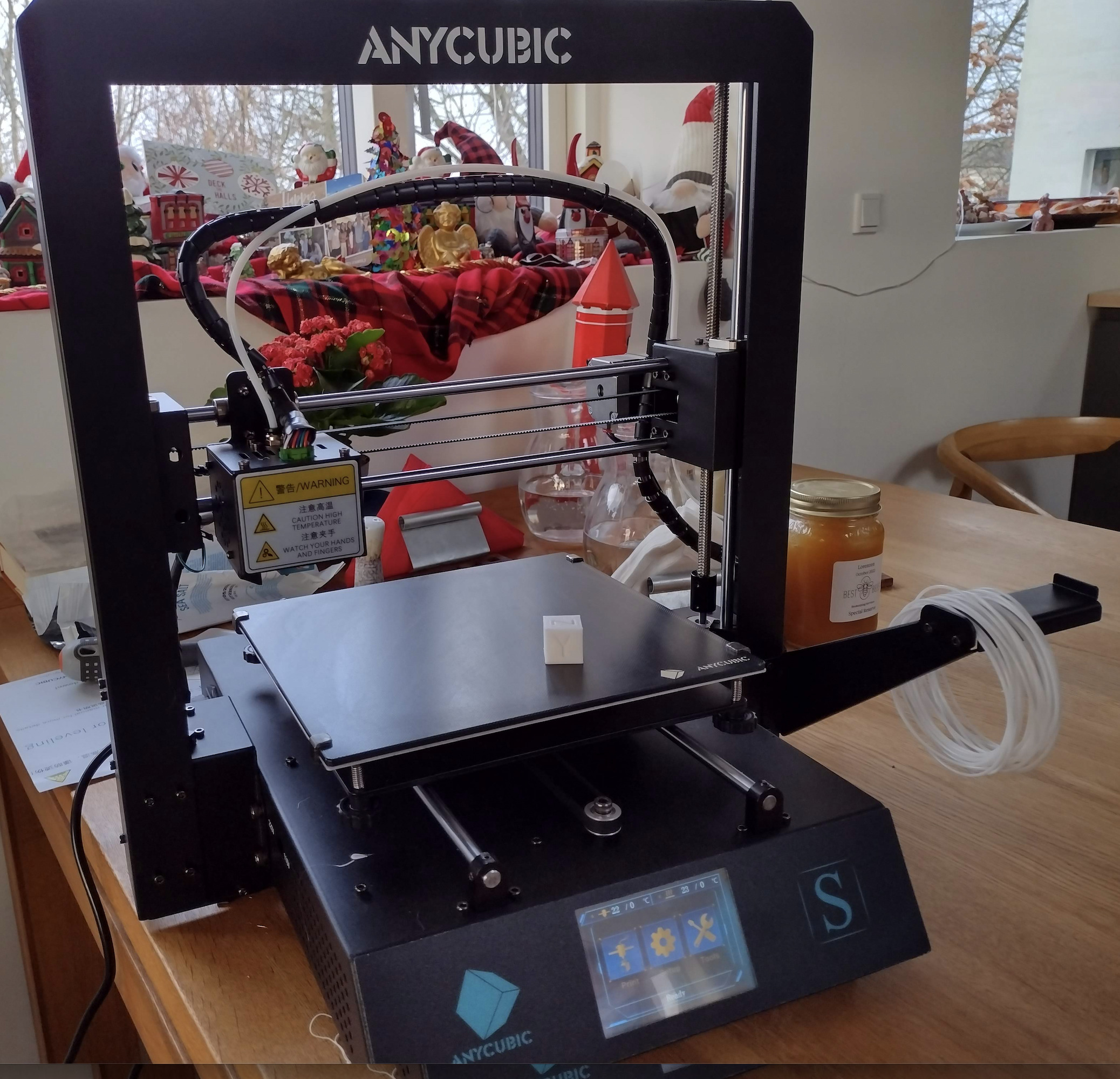 Dette er bestemt ikke verdens bedste eller hurtigste printer, den bruger kun 8-bit CPU. Jeg ville nok have fortrukket en Ender 3, men prisen var rigtig
Det største ulempe ved at mainboard kun er 8-bit er i mine øjne at der ikke er en hurtig USB forbindelse, og man dermed ikke effektivt kan kopiere filer ned på SD korted via net/USB. Så jeg plejer at flytte SD-card til min PC kopiere gcode filen ned på det, og flytte det tilbage til printeren, og starte printet.
Det koster betydelig investering, både i HW (32bit CPU upgrade) og/eller tid, at få sin printer til printe hurtigere, det er meget enklere/billigere blot at have flere billige printere printe samtidigt, ihvertfald sålænge man kan få dem til den pris.
Nedenfor er link til resources om denne printer.
- Anycubic i3 Mega s
- User Manual
- Knutwurst’s i3 MEGA M/S/P/X/Chiron/4MP2 Hybrid Firmware (based on Marlin 2.1.x)
- Pronterface.com GUI printer kontrol, installering
- Cura fra Ultimaker slicing software til at genere Gcode fra .stl filer
- Prusa Slic3r slicing software til at genere Gcode fra .stl filer
- OctoPi – Octoprint on Raspberry Pi – WEB baseret access/monitoring af 3D-printer.
 |
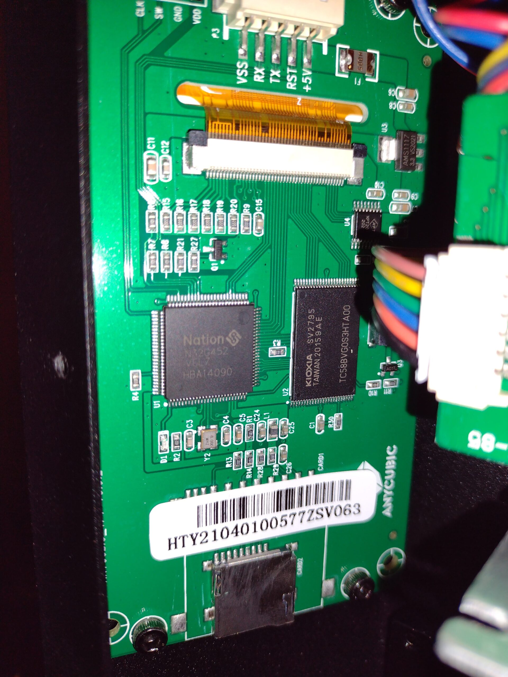 |
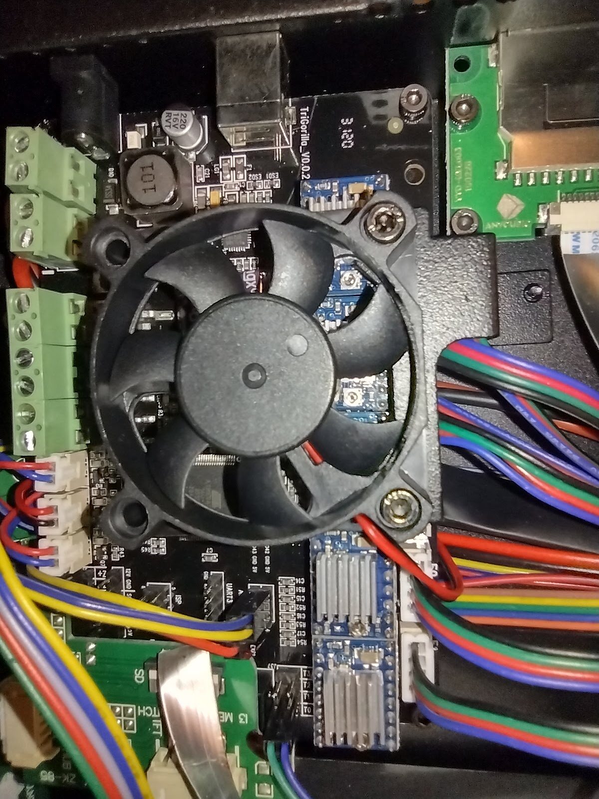
- Mega S (second generation with Anycubic 0.0.2 display)
- TriGorilla V0.0.2 main board
- P300W12V power supply
- Anycubic 0.0.2 TFT touchscreen, Desvære kan menuen ikke opdateres, der har været forsøg på skifte firmware på TFT-controlleren, men endnu uden resultat, det enkleste vil være at skifte til RepRap LCD 2004/12864
- YouTube: … Dual screen setup (tutorial)
- YouTube: … Customising the TFT Firmware DWIN DDGUS …
- github.com/bigtreetech/BIGTREETECH-TouchScreenFirmware/discussions/2332
- github.com/etet100/BTT-TouchScreenFirmware-Anycubic-4MAX-PRO-2
Upgrades
- Udskift blæserne med lydløse versioner
- BLTouch eller anden automatisk bedleveling
- Nedgrader fra touchskærm til 2004 eller 12864 LCD Aliexpress 41kr
- Upgrade af steppermotor driver fra A4988 til TMC2208 link
- Justere 12v spændingsforsyningn op til f.ex 15v muliggør 50 % mere effekt
- Upgrade softwaren på det nuværende mainboard til Marlin 2, plus Raspberry Pi med Octoprint eller ESP-32 Wifi
- Upgrade af softwaren på det nuværende mainboard til Klipper, kræver en Linux ARM SoC til hoved progrsmmet, giver hurtig access fra nettet.
- Opgradere til 32-bits mainboard med Marlin 2, giver også hurtigere adgang via net/USB
Marlin vs Klipper
Helt fra begyndelsen har jeg brugt up-to-date self-compiled versioner af Marlin på 8 bit Atmega-2560 processorer, men jeg har endnu ikke prøvet Klipper.
Jeg har også et par 32-bits mainboard liggende i skuffen som det var planen at jeg skulle bruge i min perfekte 3D printer.
Min eneste klage over Marlin på Atmega-2560, er den langsomme overførsel af filer via USB, et skifte til Klipper (på det originale 8-bit mainboard), eller et skifte af mainboard til 32-bit ville forbedre dette betydeligt.
YouTube: How FAST is KLIPPER REALLY? …CHEAP BED SLINGERS ?!
Ovenstående video beskriver at et skifte til Klipper vil halvere print tiden, så der er nok ingen tvivl om at den langsigtede løsning er at skifte til Klipper.
]]>- MKS GEN v1.3 using atmega2560 as used on Tevo Tarantula
- Melzi 2.0 using atmega1284p as used on Tronxy X1
- SKR v1.1 using lpc1768 on home made Prusa i3 Clone
PlatformIO already have a separate directory tree for object files and binaries.
We will have a subdir per board which contains the configuration files, and the platformio.ini, The platformio.ini is comparable to a Makefile, just different syntactic suger.
To do this I want a way to have per printer Configuration.h and Configuration_adv.h files. while sharing the rest. A very simple way to achieve that is to just add -Iprinter_conf_dir fot the C-preprocessor and have it be first in the include search path – but how do we do that in the PlatformIO world?
There is an option build_flags most options will make it into C*FLAGS, but you have no control of the order so no luck here.
With the option extra_scripts you can write your own code to change environment variables and how the system works. To figure out what we can do we create a simple platformio.ini file
[platformio]
src_dir = ../Marlin-git/Marlin
boards_dir = ../Marlin-git/buildroot/share/PlatformIO/boards

[env]
platform = atmelavr
framework = arduino
board = sanguino_atmega1284p
src_filter =  +<src/*> -<src/config> -<src/HAL> +<src/HAL/shared>

[env:show_env]
extra_scripts = pre:show_env.py
print_env.py is a small script which looks like this
Import("env")
print(env.Dump())
When executing “pio run -e show_env” we will see something like this
Processing show_env (platform: atmelavr; framework: arduino; board: sanguino_atmega1284p)
-----------------------------------------------------------------------------------------------------------------
Verbose mode can be enabled via `-v, --verbose` option
{ 'AR': 'ar',
  'ARCOM': '$AR $ARFLAGS $TARGET ${_long_sources_hook(__env__, SOURCES)}',
  'ARCOMSTR': 'Archiving $TARGET',
  'ARFLAGS': ['rc'],
  'AS': 'as',
  'ASCOM': '$AS $ASFLAGS -o $TARGET $SOURCES',
  'ASCOMSTR': 'Compiling $TARGET',
  'ASFLAGS': [],
  'ASPPCOM': '$CC $ASPPFLAGS $CPPFLAGS $_CPPDEFFLAGS '
             '${_long_incflags_hook(__env__, _CPPINCFLAGS)} -c -o $TARGET '
             '$SOURCES',
  'ASPPCOMSTR': 'Compiling $TARGET',
  'ASPPFLAGS': '$ASFLAGS',
  'BOARD': 'sanguino_atmega1284p',
  'BOARD_F_CPU': '16000000L',
  'BOARD_MCU': 'atmega1284p',
  'BUILDERS': { 'Library': ,
                'LoadableModule': ,
                'Object': ,
                'Program': ,
                'SharedLibrary': ,
                'SharedObject': ,
                'StaticLibrary': ,
                'StaticObject': },
  'BUILD_CACHE_DIR': None,
  'BUILD_DIR': '$PROJECT_BUILD_DIR/$PIOENV',
  'BUILD_SCRIPT': '/t470/peter/.platformio/platforms/atmelavr/builder/main.py',
  'BUILD_SRC_DIR': '$BUILD_DIR/src',
  'BUILD_TEST_DIR': '$BUILD_DIR/test',
  'CC': 'cc',
  'CCCOM': '$CC -o $TARGET -c $CFLAGS $CCFLAGS $_CCCOMCOM $SOURCES',
  'CCCOMSTR': 'Compiling $TARGET',
  'CCFLAGS': [],
  'CFILESUFFIX': '.c',
  'CFLAGS': [],
  'COMPILATIONDB_PATH': '$BUILD_DIR/compile_commands.json',
  'CONFIGUREDIR': '#/.sconf_temp',
  'CONFIGURELOG': '#/config.log',
  'CPPDEFPREFIX': '-D',
  'CPPDEFSUFFIX': '',
  'CPPSUFFIXES': [ '.c',
                   '.C',
                   '.cxx',
                   '.cpp',
                   '.c++',
                   '.cc',
                   '.h',
                   '.H',
                   '.hxx',
                   '.hpp',
                   '.hh',
                   '.F',
                   '.fpp',
                   '.FPP',
                   '.m',
                   '.mm',
                   '.S',
                   '.spp',
                   '.SPP',
                   '.sx'],
  'CXX': 'c++',
  'CXXCOM': '$CXX -o $TARGET -c $CXXFLAGS $CCFLAGS $_CCCOMCOM $SOURCES',
  'CXXCOMSTR': 'Compiling $TARGET',
  'CXXFILESUFFIX': '.cc',
  'CXXFLAGS': [],
  'DSUFFIXES': ['.d'],
  'Dir': ,
  'Dirs': ,
  'ENV': ...
  'ESCAPE': ,
  'FRAMEWORKPATH': [],
  'FRAMEWORKS': [],
  'File': ,
  'HOST_ARCH': None,
  'HOST_OS': None,
  'IDLSUFFIXES': ['.idl', '.IDL'],
  'INCPREFIX': '-I',
  'INCSUFFIX': '',
  'LDMODULE': '$SHLINK',
  'LDMODULECOM': '$LDMODULE -o $TARGET $LDMODULEFLAGS $__LDMODULEVERSIONFLAGS '
                 '$__RPATH $SOURCES $_LIBDIRFLAGS $_LIBFLAGS',
  'LDMODULEEMITTER': [],
  'LDMODULEFLAGS': '$SHLINKFLAGS',
  'LDMODULENOVERSIONSYMLINKS': '$SHLIBNOVERSIONSYMLINKS',
  'LDMODULEPREFIX': '$SHLIBPREFIX',
  'LDMODULESUFFIX': '$SHLIBSUFFIX',
  'LDMODULEVERSION': '$SHLIBVERSION',
  'LIBDIRPREFIX': '-L',
  'LIBDIRSUFFIX': '',
  'LIBLINKPREFIX': '-l',
  'LIBLINKSUFFIX': '',
  'LIBPATH': ['$BUILD_DIR'],
  'LIBPREFIX': 'lib',
  'LIBPREFIXES': ['$LIBPREFIX'],
  'LIBSOURCE_DIRS': [ '/net/y/y/3D/Marlin-2.0.x-git/Tronxy_X1/test/lib',
                      '$PROJECT_LIBDEPS_DIR/$PIOENV',
                      '/t470/peter/.platformio/lib'],
  'LIBSUFFIX': '.a',
  'LIBSUFFIXES': ['$LIBSUFFIX', '$SHLIBSUFFIX'],
  'LINK': '$SMARTLINK',
  'LINKCOM': '$LINK -o $TARGET $LINKFLAGS $__RPATH '
             '${_long_sources_hook(__env__, SOURCES)} $_LIBDIRFLAGS $_LIBFLAGS',
  'LINKCOMSTR': 'Linking $TARGET',
  'LINKFLAGS': [],
  'MAXLINELENGTH': 128072,
  'OBJPREFIX': '',
  'OBJSUFFIX': '.o',
  'PIOENV': 'show_env',
  'PIOFRAMEWORK': ['arduino'],
  'PIOPLATFORM': 'atmelavr',
  'PLATFORM': 'posix',
  'PLATFORM_MANIFEST': '/t470/peter/.platformio/platforms/atmelavr/platform.json',
  'PROGNAME': 'program',
  'PROGPREFIX': '',
  'PROGSUFFIX': '',
  'PROG_PATH': '$BUILD_DIR/$PROGNAME$PROGSUFFIX',
  'PROJECTDATA_DIR': '/net/y/y/3D/Marlin-2.0.x-git/Tronxy_X1/test/data',
  'PROJECTSRC_DIR': '/net/y/y/3D/Marlin-2.0.x-git/Marlin',
  'PROJECT_BUILD_DIR': '/net/y/y/3D/Marlin-2.0.x-git/Tronxy_X1/test/.pio/build',
  'PROJECT_CONFIG': '/net/y/y/3D/Marlin-2.0.x-git/Tronxy_X1/test/platformio.ini',
  'PROJECT_CORE_DIR': '/t470/peter/.platformio',
  'PROJECT_DATA_DIR': '/net/y/y/3D/Marlin-2.0.x-git/Tronxy_X1/test/data',
  'PROJECT_DIR': '/net/y/y/3D/Marlin-2.0.x-git/Tronxy_X1/test',
  'PROJECT_INCLUDE_DIR': '/net/y/y/3D/Marlin-2.0.x-git/Tronxy_X1/test/include',
  'PROJECT_LIBDEPS_DIR': '/net/y/y/3D/Marlin-2.0.x-git/Tronxy_X1/test/.pio/libdeps',
  'PROJECT_PACKAGES_DIR': '/t470/peter/.platformio/packages',
  'PROJECT_SRC_DIR': '/net/y/y/3D/Marlin-2.0.x-git/Marlin',
  'PROJECT_TEST_DIR': '/net/y/y/3D/Marlin-2.0.x-git/Tronxy_X1/test/test',
  'PROJECT_WORKSPACE_DIR': '/net/y/y/3D/Marlin-2.0.x-git/Tronxy_X1/test/.pio',
  'PSPAWN': ,
  'PYTHONEXE': '/home/peter/.platformio/penv/bin/python',
  'RANLIB': 'ranlib',
  'RANLIBCOM': '$RANLIB $RANLIBFLAGS $TARGET',
  'RANLIBCOMSTR': 'Indexing $TARGET',
  'RANLIBFLAGS': [],
  'RDirs': ,
  'SCANNERS': [],
  'SHCC': '$CC',
  'SHCCCOM': '$SHCC -o $TARGET -c $SHCFLAGS $SHCCFLAGS $_CCCOMCOM $SOURCES',
  'SHCCFLAGS': ['$CCFLAGS'],
  'SHCFLAGS': ['$CFLAGS'],
  'SHCXX': '$CXX',
  'SHCXXCOM': '$SHCXX -o $TARGET -c $SHCXXFLAGS $SHCCFLAGS $_CCCOMCOM $SOURCES',
  'SHCXXFLAGS': ['$CXXFLAGS'],
  'SHELL': 'sh',
  'SHLIBEMITTER': [],
  'SHLIBPREFIX': '$LIBPREFIX',
  'SHLIBSUFFIX': '.so',
  'SHLINK': '$LINK',
  'SHLINKCOM': '$SHLINK -o $TARGET $SHLINKFLAGS $__SHLIBVERSIONFLAGS $__RPATH '
               '$SOURCES $_LIBDIRFLAGS $_LIBFLAGS',
  'SHLINKFLAGS': ['$LINKFLAGS', '-shared'],
  'SHOBJPREFIX': '$OBJPREFIX',
  'SHOBJSUFFIX': '.os',
  'SMARTLINK': ,
  'SPAWN': ,
  'SRC_FILTER': [ '+ - - + '
                  '+'],
  'STATIC_AND_SHARED_OBJECTS_ARE_THE_SAME': 0,
  'TARGET_ARCH': None,
  'TARGET_OS': None,
  'TEMPFILE': ,
  'TEMPFILEARGJOIN': ' ',
  'TEMPFILEPREFIX': '@',
  'TOOLS': [ 'ar',
             'as',
             'cc',
             'c++',
             'link',
             'platformio',
             'pioplatform',
             'pioproject',
             'piomaxlen',
             'piolib',
             'pioupload',
             'piomisc',
             'pioide',
             'piosize'],
  'UNIX_TIME': 1587916285,
  'UPLOAD_PROTOCOL': 'arduino',
  'UPLOAD_SPEED': 115200,
  '_CCCOMCOM': '$CPPFLAGS $_CPPDEFFLAGS ${_long_incflags_hook(__env__, '
               '_CPPINCFLAGS)}',
  '_CPPDEFFLAGS': '${_defines(CPPDEFPREFIX, CPPDEFINES, CPPDEFSUFFIX, '
                  '__env__)}',
  '_CPPINCFLAGS': '$( ${_concat(INCPREFIX, CPPPATH, INCSUFFIX, __env__, RDirs, '
                  'TARGET, SOURCE)} $)',
  '_LIBDIRFLAGS': '$( ${_concat(LIBDIRPREFIX, LIBPATH, LIBDIRSUFFIX, __env__, '
                  'RDirs, TARGET, SOURCE)} $)',
  '_LIBFLAGS': '${_stripixes(LIBLINKPREFIX, LIBS, LIBLINKSUFFIX, LIBPREFIXES, '
               'LIBSUFFIXES, __env__)}',
  '__DRPATH': '$_DRPATH',
  '__DSHLIBVERSIONFLAGS': '${__libversionflags(__env__,"DSHLIBVERSION","_DSHLIBVERSIONFLAGS")}',
  '__LDMODULEVERSIONFLAGS': '${__libversionflags(__env__,"LDMODULEVERSION","_LDMODULEVERSIONFLAGS")}',
  '__RPATH': '$_RPATH',
  '__SHLIBVERSIONFLAGS': '${__libversionflags(__env__,"SHLIBVERSION","_SHLIBVERSIONFLAGS")}',
  '__libversionflags': ,
  '_concat': ,
  '_defines': ,
  '_long_incflags_hook': ,
  '_long_sources_hook': ,
  '_stripixes': ,
  'toolpath': [ '/t470/peter/.platformio/penv/lib/python3.6/site-packages/platformio/builder/tools']}
CONFIGURATION: https://docs.platformio.org/page/boards/atmelavr/sanguino_atmega1284p.html
PLATFORM: Atmel AVR 2.0.0 > Sanguino ATmega1284p (16MHz)
HARDWARE: ATMEGA1284P 16MHz, 16KB RAM, 127KB Flash
PACKAGES:
 - framework-arduino-avr 5.0.0
 - toolchain-atmelavr 1.50400.190710 (5.4.0)
Converting Marlin.ino
LDF: Library Dependency Finder -> http://bit.ly/configure-pio-ldf
LDF Modes: Finder ~ chain, Compatibility ~ soft
Found 5 compatible libraries
Scanning dependencies...
Dependency Graph
|--  1.0
|--  1.0
Building in release mode
...
Lots of variables, focusing on CPP variables we note that ‘_CPPINCFLAGS’ most likely have the include-file-search-path, if we could only prepend -Imy_conf_dir we would be all set. Another variable PIOENV hold the name of the current environment, we can use that to our advantage, and have per environment config-files.
The script below called prepend_cpppath.py lets the compiler look in a directory with the environment name first, or if it is not present to look in the dir where platformio.ini was located. So if we put our include files there, they will be found first – mission accompliced
import os
Import("env")
if os.path.isdir(env['PIOENV']):
    incdir = env['PIOENV']
else:
    incdir = "."

env['_CPPINCFLAGS'] = "-I%s $( ${_concat(INCPREFIX, CPPPATH, INCSUFFIX, __env__, RDirs, TARGET, SOURCE)} $)" % (incdir)
With this we can create a small setup where it is convenient to have the firmware for all my 3D-printers based on the same source-code-tree. Below is how I have organized my directory layout.
 Makefile               # I like Makefile, it is like my README file
 Marlin-git/            # git clone -b 2.0.x https://github.com/MarlinFirmware/Marlin.git Marlin-git
     platformio.ini
     buildroot/
     Marlin/
         src
         Configuration.h
         Configuration_adv.h
         platformio.ini
         ...
     ...
 platformio.ini         # to compile the default setup for the printers below.
 prepend_cpppath.py
 tronxy_x1/
     Configuration.h
     Configuration_adv.h
     platformio.ini
     tronxy_x1_tiny/
         Configuration.h
         Configuration_adv.h
         platformio.ini
 tarantula/
     Configuration.h
     Configuration_adv.h
     platformio.ini
 skr-v1.1/
     Configuration.h
     Configuration_adv.h
     platformio.ini
 build/                 # Files generated by PlatformIO
     skr-v1.1/
     tarantula/
     tronxy_x1/
 lib/                   # libraries put here will override those below
 libdeps/               # libraries downloaded by PlatformIO automagically
     skr-v1.1/
     tarantula/
     tronxy_x1/
The content of the tronxy_x1/platformio.ini
# Marlin-2 via PlatformIO for Tronxy X1
# tronxy_x1: using NewLiquidCrystal over I2C via Wire
# tronxy_x1_tiny: using LCD_I2C_Tiny via SoftI2CMaster

[my]
top          = ..
hal_dir      = ${my.top}/Marlin-git/Marlin/src/HAL
script_dir   = ${my.top}/Marlin-git/buildroot/share/PlatformIO/scripts

[platformio]
libdeps_dir  = ${my.top}/libdeps
build_dir    = ${my.top}/build
lib_dir      = ${my.top}/lib
src_dir      = ${my.top}/Marlin-git/Marlin
boards_dir   = ${my.top}/Marlin-git/buildroot/share/PlatformIO/boards
default_envs = tronxy_x1, tronxy_x1_tiny

[common]
default_src_filter = + - - + +
extra_scripts = pre:${my.script_dir}/common-cxxflags.py
build_flags = -fmax-errors=5 -g -D__MARLIN_FIRMWARE__ -fmerge-all-constants -DUSE_MAKE
lib_deps      = LiquidCrystal

[env]
platform      = atmelavr
framework     = arduino
board         = sanguino_atmega1284p
build_flags   = ${common.build_flags}
lib_deps      = ${common.lib_deps}
monitor_speed = 250000
upload_speed  = 115200
src_filter    = ${common.default_src_filter}
extra_scripts = pre:../prepend_cpppath.py

[env:show_env]
extra_scripts = pre:../show_env.py

[env:tronxy_x1]
build_flags   = ${common.build_flags}
  -DLCD_I2C
  -DCUSTOM_MACHINE_NAME="\"Tronxy X1 24Apr2020\""
lib_deps      = ${common.lib_deps}

[env:tronxy_x1_tiny]
# with platformio saves text=246 data=8 bss=1
# Arduino the saving were text=642 data=18 bss=182
build_flags   = ${common.build_flags}
  -DLCD_I2C_TINY
  -DCUSTOM_MACHINE_NAME="\"Tronxy x1 24Apr2020\""
lib_deps      =
  SoftI2CMaster=https://github.com/todbot/SoftI2CMaster.git
  LiquidCrystal_I2C_Tiny=https://github.com/SpenceKonde/LiquidCrystal_I2C_Tiny.git
lib_ignore    = Wire
The special thing here is that I can be working on a version using LCD_Tiny to save some flash which is the bottleneck on this CPU
The top platformio.ini have all that is needed to compile firmware for all my 3D-printers (envs), the file is below:
# Marlin Firmware for my 3D printers
# PlatformIO Configuration File
#
# For detailed documentation with EXAMPLES:
# http://docs.platformio.org/en/latest/projectconf.html

[my]
top          = .
hal_dir      = ${my.top}/Marlin-git/Marlin/src/HAL
script_dir   = ${my.top}/Marlin-git/buildroot/share/PlatformIO/scripts

[platformio]
libdeps_dir  = ${my.top}/libdeps
build_dir    = ${my.top}/build
lib_dir      = ${my.top}/lib
src_dir      = ${my.top}/Marlin-git/Marlin
boards_dir   = ${my.top}/Marlin-git/buildroot/share/PlatformIO/boards
default_envs = tronxy_x1, tarantula

[common]
default_src_filter = +<src/*> -<src/config> -<src/HAL> +<src/HAL/shared>
extra_scripts = pre:${my.script_dir}/common-cxxflags.py
build_flags = -fmax-errors=5 -g -D__MARLIN_FIRMWARE__ -fmerge-all-constants
lib_deps = LiquidCrystal

[env]
framework     = arduino
build_flags   = ${common.build_flags}
lib_deps      = ${common.lib_deps}
monitor_speed = 250000
upload_speed  = 115200
extra_scripts = pre:prepend_cpppath.py

[env:show_env]
extra_scripts = pre:show_env.py

[env:tarantula]
platform      = atmelavr
board         = megaatmega2560
src_filter    = ${common.default_src_filter} +<src/HAL/AVR>
build_flags   = ${common.build_flags}
  -DCUSTOM_MACHINE_NAME="\"Tarantula 26Apr2020\""

[env:tronxy_x1]
platform      = atmelavr
board         = sanguino_atmega1284p
src_filter    = ${common.default_src_filter} +<src/HAL/AVR>
build_flags   = ${common.build_flags}
  -DLCD_I2C
  -DCUSTOM_MACHINE_NAME="\"Tronxy X1 24Apr2020\""


#
# NXP LPC176x ARM Cortex-M3
#
[env:LPC1768]
platform          = https://github.com/p3p/pio-nxplpc-arduino-lpc176x/archive/0.1.2.zip
board             = nxp_lpc1768
build_flags       = -DU8G_HAL_LINKS -I${my.hal_dir}/LPC1768/include -I${my.hal_dir}/LPC1768/u8g ${common.build_flags}
# debug options for backtrace
#  -funwind-tables
#  -mpoke-function-name
lib_ldf_mode      = off
lib_compat_mode   = strict
extra_scripts     = ${my.hal_dir}/LPC1768/upload_extra_script.py
src_filter        = ${common.default_src_filter} +<src/HAL/LPC1768>
lib_deps          = LiquidCrystal
I haven’t made up my mind if I like PlatformIO yet.
My first reaction was: why bother, we have Makefiles, and OpenWRT and BSD-ports have showed us how to get/compile full systems long before PlatformIO was invented.
On the other hand it only took me a day or two to figure out a solution to my problem, and it only required a few lines of code, so it seems PlatformIO is highly flexible.
The real power with PlatformIO (and OpenWrt Makefiles) is that somebody already did most of the work and integrated everything for you, so you can create one of their precooked meals without much effort. I seem to always to end up with a desire to use it a little differently.
The good news is: if PlatformIO do not do work the way you think is should work – you can fix it, without too much effort !
If you like me prefer the commandline over the Arduino-IDE or other click-systems, you will be better of adopting the PlatformIO to compile Marlin, than try to get the supplied Makefile to do what you want.
Stay tuned, there might be more coming,
]]>This post will cover how I set up my system so I can compile Marlin for multiple mainboards , while sharing the same source-code-tree, the boards/printers covered here are:
- MKS GEN v1.3 using atmega2560 as used on Tevo Tarantula
- Melzi 2.0 using atmega1284p as used on Tronxy X1
Marlin has a Makefile which with a little tweaking can compile the firmware, but there is no provision to have a common source-tree to compile for different boards/cpu’s. Let us change that.
The goal is to have a subdir per board which contains the configuration files, and object-files used during compilation. Here is how I would compile new firmware for the two printers :
$ cd Marlin-2.0.x-git/Marlin/
$ ls -l . Tarantula Tronxy_X1
-rw-r--r--  1 peter peter 124938 Mar 19 21:32 Configuration_adv.h
-rw-r--r--  1 peter peter  82430 Mar 19 21:34 Configuration.h
drwxr-xr-x  2 peter peter      3 Feb 27  2019 lib
-rw-r--r--  1 peter peter  30323 Mar 20 11:39 Makefile
-rw-r--r--  1 peter peter   1922 Mar 11 19:12 Marlin.ino
drwxr-xr-x 12 peter peter     15 Mar 19 21:31 src
drwxr-xr-x  3 peter peter      7 Mar 20 13:12 Tarantula
drwxr-xr-x  2 peter peter      5 Mar 20 13:13 Tronxy_X1
-rw-r--r--  1 peter peter   2535 Mar 11 19:12 Version.h

Tarantula:
-rw-r--r-- 1 peter peter 124225 Mar 20 11:34 Configuration_adv.h
-rw-r--r-- 1 peter peter  97284 Mar 20 12:19 Configuration.h
-rw-r--r-- 1 peter peter   1272 Mar 20 12:52 Makefile

Tronxy_X1:
-rw-r--r-- 1 peter peter 124934 Mar 19 20:12 Configuration_adv.h
-rw-r--r-- 1 peter peter  84251 Mar 20 09:59 Configuration.h
-rw-r--r-- 1 peter peter   1614 Mar 20 12:53 Makefile
$ cd Tarantula; make
...
   text    data     bss     dec     hex filename
 162226     370    4331  166927   28c0f objs/Tarantula.elf

$ cd ../Tronxy_X1; make
...

   text    data     bss     dec     hex filename
 129920     396    3835  134151   20c07 objs/Tronxy_X1.elf
The per board Makefiles I created are quite small, it includes the standard Makefile which contains the bulk of the rules, The Configuration files typically comes from github.com/MarlinFirmware/Configurations/archive/bugfix-2.0.x.zip and the Marlin source is from github.com/MarlinFirmware/Marlin
Makefile for Tevo Tarantula
# Makefile for Tevo Tarantula
 ARDUINO_INSTALL_DIR  = $(HOME)/Arduino-1.8.12-x86_64
 HARDWARE_MOTHERBOARD = 1110  # MKS v1.3
 MCU                  = atmega2560
 HARDWARE_VARIANT     = arduino
 VPATH += .
 VPATH += ..
 VPATH += objs
 SRC_DIR         = ../src
 BUILD_DIR       = objs
 # Note no space allowed before comment #
 LIQUID_CRYSTAL ?= 1# DEFAULT 6 io-pins directly control
 U8GLIB         ?= 0# we use a character LCD
 TMC            ?= 0# not using Trinamic TMCStepper
 AVRDUDE_CONF    = /etc/avrdude.conf
 UPLOAD_RATE     = 115200
 include ../Makefile
Makefile for Tronxy X1, LCD via i2c
For my Tronxy X1 the Makefile is a bit more complicated, mostly because I have modded the hardware, The Tronxy X1 is using an atmeaga1284p as CPU, the little sister to the atmega2560 with less pins and half as much FLASH. I needed an extra io-pin for a filament sensor, but there is no unused inputs, so I converted the LCD to be accessed via i2c, which uses 2 io-pins instead of 6. Marlin has support to use a 20×4 character lcd connected via i2c and a pcf8574 so the change is not complicated, but FLASH is limited, so I had to replace the i2c-driver with a leaner one.
# Makefile for Tronxy X1
# with LCD via I2C
 ARDUINO_INSTALL_DIR  = $(HOME)/Arduino-1.8.12-x86_64
 HARDWARE_MOTHERBOARD = 1502  # Melzi
 MCU                  = atmega1284p
 HARDWARE_VARIANT     = Sanguino
 HARDWARE_SUB_VARIANT = sanguino
 VPATH += .
 VPATH += ..
 VPATH += objs
 MightyCore = $(HOME)/MightyCore
 VPATH += $(MightyCore)/avr/cores/MCUdude_corefiles
 VPATH += $(MightyCore)/avr/variants/sanguino
 VPATH += $(MightyCore)/avr/libraries/SPI/src
 SRC_DIR      = ../src
 BUILD_DIR    = objs
 # Note no space allowed before comment #
 LIQUID_CRYSTAL          ?= 0# 6 io-pins directly controlling the LCD
 LIQUID_CRYSTAL_I2C      ?= 0# LCD connected vi i2c pcf8574
 LIQUID_CRYSTAL_I2C_TINY ?= 1# as above saves text=642 data=18 bss=182
 U8GLIB                  ?= 0# we use character LCD
 TMC                     ?= 0# not using Trinamic TMCStepper
 ifeq ($(LIQUID_CRYSTAL_I2C), 1)
   VPATH += $(MightyCore)/avr/libraries/Wire/src
   VPATH += $(MightyCore)/avr/libraries/Wire/src/utility
   VPATH += $(HOME)/Arduino/libraries/LiquidCrystal_I2C
   LIB_SRC += twi.c
   LIB_CXXSRC += Wire.cpp
   LIB_CXXSRC += LiquidCrystal_I2C.cpp
 endif
 ifeq ($(LIQUID_CRYSTAL_I2C_TINY), 1)
   VPATH += $(HOME)/Arduino/libraries/SoftI2CMaster
   VPATH += $(HOME)/Arduino/libraries/LiquidCrystal_I2C_Tiny
   LIB_CXXSRC += SoftI2CMaster.cpp
   LIB_CXXSRC += LiquidCrystal_I2C_Tiny.cpp
 endif
 AVRDUDE_CONF = /etc/avrdude.conf
 UPLOAD_RATE  = 115200
 include ../Makefile
Modifcation to Marlin Makefile
My Makefiles over-ride some of settings used in the standard Makefile which is included in the end. This requires a few trivial changes is in the Marlin Makefile, ?= means that variable will only be set if not set already, and += appends a setting instead of just overriding it, some #ifdef to opt out of using the standard LCD-library, and lastly SRC_DIR can be set to direct the Makefile where to find the source-files, see the diffs below:
diff --git a/Marlin/Makefile b/Marlin/Makefile
index fcd763881..4a295d5bc 100644
--- a/Marlin/Makefile
+++ b/Marlin/Makefile
@@ -80,6 +80,9 @@ UPLOAD_PORT        ?= /dev/ttyUSB0
 #on linux it is best to put an absolute path like /home/username/tmp .
 BUILD_DIR          ?= applet

+# This defines whether LiquidCrystal support will be built
+LIQUID_CRYSTAL     ?= 1
+
 # This defines whether Liquid_TWI2 support will be built
 LIQUID_TWI2        ?= 0

@@ -529,12 +532,14 @@ TARGET = $(notdir $(CURDIR))
 # source files, but for Marlin 2.0, we use VPATH only for arduino
 # library files.

-VPATH = .
+VPATH += .
 VPATH += $(BUILD_DIR)
 VPATH += $(HARDWARE_SRC)

 ifeq ($(HARDWARE_VARIANT), $(filter $(HARDWARE_VARIANT),arduino Teensy Sanguino))
+ifeq ($(LIQUID_CRYSTAL), 1)
 VPATH += $(ARDUINO_INSTALL_DIR)/hardware/marlin/avr/libraries/LiquidCrystal/src
+endif
 VPATH += $(ARDUINO_INSTALL_DIR)/hardware/marlin/avr/libraries/SPI
 endif

@@ -546,7 +551,9 @@ ifeq ($(IS_MCU),1)
   VPATH += $(ARDUINO_INSTALL_DIR)/hardware/arduino/avr/libraries/SoftwareSerial/src
 endif

+ifeq ($(LIQUID_CRYSTAL), 1)
 VPATH += $(ARDUINO_INSTALL_DIR)/libraries/LiquidCrystal/src
+endif
 ifeq ($(LIQUID_TWI2), 1)
 VPATH += $(ARDUINO_INSTALL_DIR)/libraries/Wire
 VPATH += $(ARDUINO_INSTALL_DIR)/libraries/Wire/utility
@@ -593,7 +600,7 @@ else
   VPATH += $(ARDUINO_INSTALL_DIR)/hardware/$(HARDWARE_VARIANT)/variants/$(HARDWARE_SUB_VARIANT)
 endif

-LIB_SRC = wiring.c \
+LIB_SRC += wiring.c \
   wiring_analog.c wiring_digital.c \
   wiring_shift.c WInterrupts.c hooks.c

@@ -604,19 +611,21 @@ else
 endif

 ifeq ($(HARDWARE_VARIANT), Teensy)
-  LIB_SRC = wiring.c
+  LIB_SRC += wiring.c
   VPATH += $(ARDUINO_INSTALL_DIR)/hardware/teensy/cores/teensy
 endif

-LIB_CXXSRC = WMath.cpp WString.cpp Print.cpp SPI.cpp
+LIB_CXXSRC += WMath.cpp WString.cpp Print.cpp SPI.cpp

 ifeq ($(NEOPIXEL), 1)
   LIB_CXXSRC += Adafruit_NeoPixel.cpp
 endif

-ifeq ($(LIQUID_TWI2), 0)
+ifeq ($(LIQUID_CRYSTAL), 1)
   LIB_CXXSRC += LiquidCrystal.cpp
-else
+endif
+
+ifeq ($(LIQUID_TWI2), 1)
   LIB_SRC += twi.c
   LIB_CXXSRC += Wire.cpp LiquidTWI2.cpp
 endif
@@ -708,7 +717,7 @@ CXXWARN = -Wall                     -Wno-packed-bitfield-compat -Wno-pragmas -Wu
 CTUNING = -fsigned-char -funsigned-bitfields -fno-exceptions \
           -fshort-enums -ffunction-sections -fdata-sections
 ifneq ($(HARDWARE_MOTHERBOARD),)
-  CTUNING += -DMOTHERBOARD=${HARDWARE_MOTHERBOARD}
+#  CTUNING += -DMOTHERBOARD=${HARDWARE_MOTHERBOARD}
 endif
 #CEXTRA = -Wa,-adhlns=$(<:.c=.lst)
 CXXEXTRA = -fno-use-cxa-atexit -fno-threadsafe-statics -fno-rtti
@@ -730,9 +739,9 @@ endif
 AVRDUDE_PORT = $(UPLOAD_PORT)
 AVRDUDE_WRITE_FLASH = -Uflash:w:$(BUILD_DIR)/$(TARGET).hex:i
 ifeq ($(shell uname -s), Linux)
-  AVRDUDE_CONF = /etc/avrdude/avrdude.conf
+  AVRDUDE_CONF ?= /etc/avrdude/avrdude.conf
 else
-  AVRDUDE_CONF = $(ARDUINO_INSTALL_DIR)/hardware/tools/avr/etc/avrdude.conf
+  AVRDUDE_CONF ?= $(ARDUINO_INSTALL_DIR)/hardware/tools/avr/etc/avrdude.conf
 endif
 AVRDUDE_FLAGS = -D -C$(AVRDUDE_CONF) \
   -p$(MCU) -P$(AVRDUDE_PORT) -c$(AVRDUDE_PROGRAMMER) \
@@ -741,15 +750,17 @@ AVRDUDE_FLAGS = -D -C$(AVRDUDE_CONF) \
 # Since Marlin 2.0, the source files may be distributed into several
 # different directories, so it is necessary to find them recursively

-SRC    = $(shell find src -name '*.c'   -type f)
-CXXSRC = $(shell find src -name '*.cpp' -type f)
+SRC_DIR ?= src
+
+SRC    = $(shell find $(SRC_DIR) -name '*.c'   -type f)
+CXXSRC = $(shell find $(SRC_DIR) -name '*.cpp' -type f)

 # Define all object files.
 OBJ  = ${patsubst %.c,   $(BUILD_DIR)/arduino/%.o, ${LIB_SRC}}
 OBJ += ${patsubst %.cpp, $(BUILD_DIR)/arduino/%.o, ${LIB_CXXSRC}}
 OBJ += ${patsubst %.S,   $(BUILD_DIR)/arduino/%.o, ${LIB_ASRC}}
-OBJ += ${patsubst %.c,   $(BUILD_DIR)/%.o, ${SRC}}
-OBJ += ${patsubst %.cpp, $(BUILD_DIR)/%.o, ${CXXSRC}}
+OBJ += ${patsubst $(SRC_DIR)/%.c,   $(BUILD_DIR)/src/%.o, ${SRC}}
+OBJ += ${patsubst $(SRC_DIR)/%.cpp, $(BUILD_DIR)/src/%.o, ${CXXSRC}}

 # Define all listing files.
 LST = $(LIB_ASRC:.S=.lst) $(LIB_CXXSRC:.cpp=.lst) $(LIB_SRC:.c=.lst)
One of the include files also need to be modified to be able to find the configuration files in their new position.
diff --git a/Marlin/src/inc/MarlinConfigPre.h b/Marlin/src/inc/MarlinConfigPre.h
 index 1385f9e19..9a5d69e77 100644
 --- a/Marlin/src/inc/MarlinConfigPre.h
 +++ b/Marlin/src/inc/MarlinConfigPre.h
 @@ -34,7 +34,8 @@
  #include "../core/boards.h"
  #include "../core/macros.h"
 -#include "../../Configuration.h"
 +//#include "../../Configuration.h"
 +#include "Configuration.h"
  #ifdef CUSTOM_VERSION_FILE
    #if defined(__has_include)
 @@ -52,7 +53,8 @@
  #include HAL_PATH(../HAL, inc/Conditionals_LCD.h)
  #include "../core/drivers.h"
 -#include "../../Configuration_adv.h"
 +//#include "../../Configuration_adv.h"
 +#include "Configuration_adv.h"
  #include "Conditionals_adv.h"
  #include HAL_PATH(../HAL, inc/Conditionals_adv.h)
These changes should not change Marlins ability to be compiled under the Arduino IDE.
Changes to let Tronxy X1 access its LCD via i2c
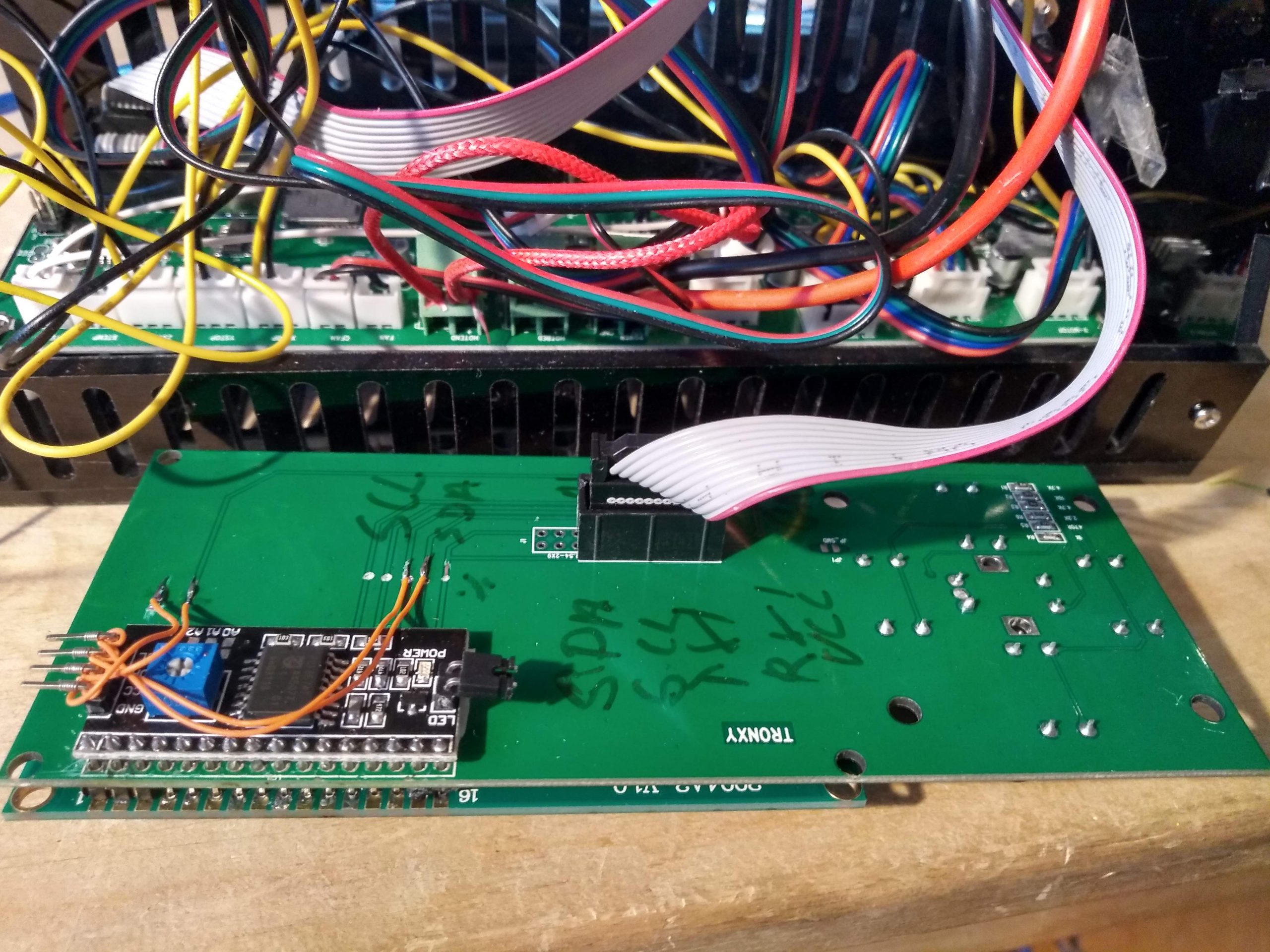 The Tronxy X1 uses a Melzi 2.0 mainboard and a 20×4 LCD with 5 buttons which is read via one analog input. I want to change the output to the LCD to go via i2c, the i2c-LCD-interface boards are available from Aliexpress for next to nothing. and takes over the control of the LCD, I just unsoldered the LCD, drilled out the holes in the current LCD/buttton-pcb, and had the connections run through to the new i2c-LCD board, scl/ada happens to be part of io-pins going to the board already, so these together with VCC and GND are connected. The buttons works as usual. Check the photo above.
The Tronxy X1 Configuration file just need a number of #define, and two files in the Marlin distribution needs an #ifdef, the diffs are below
peter@t470:Marlin> git diff src/lcd/HD44780
diff --git a/Marlin/src/lcd/HD44780/ultralcd_HD44780.cpp b/Marlin/src/lcd/HD44780/ultralcd_HD44780.cpp
index a032450ad..c71c09823 100644
--- a/Marlin/src/lcd/HD44780/ultralcd_HD44780.cpp
+++ b/Marlin/src/lcd/HD44780/ultralcd_HD44780.cpp
@@ -68,6 +68,9 @@

 #elif ENABLED(LCD_I2C_TYPE_PCA8574)

+#ifdef LCD_I2C_TINY
+  SoftI2CMaster softi2c=SoftI2CMaster(PIN_WIRE_SCL,PIN_WIRE_SDA,0);
+#endif
   LCD_CLASS lcd(LCD_I2C_ADDRESS, LCD_WIDTH, LCD_HEIGHT);

 #elif ENABLED(SR_LCD_2W_NL)
@@ -354,7 +357,11 @@ void MarlinUI::init_lcd() {
     lcd.begin(LCD_WIDTH, LCD_HEIGHT);

   #elif ENABLED(LCD_I2C_TYPE_PCA8574)
+#ifdef LCD_I2C_TINY
+    lcd.begin();
+#else
     lcd.init();
+#endif
     lcd.backlight();

   #else
diff --git a/Marlin/src/lcd/HD44780/ultralcd_HD44780.h b/Marlin/src/lcd/HD44780/ultralcd_HD44780.h
index 12bf86a16..45b38fe54 100644
--- a/Marlin/src/lcd/HD44780/ultralcd_HD44780.h
+++ b/Marlin/src/lcd/HD44780/ultralcd_HD44780.h
@@ -74,7 +74,12 @@
   #define LCD_CLASS LiquidTWI2

 #elif ENABLED(LCD_I2C_TYPE_PCA8574)
+#ifdef LCD_I2C_TINY
+  #include
+  #include
+#else
   #include
+#endif
   #define LCD_CLASS LiquidCrystal_I2C

 #elif ENABLED(SR_LCD_2W_NL)
The modification to Configuration.h, most of it is documentation.
--- Configurations-bugfix-2.0.x/config/examples/Tronxy/X1/Configuration.h	2020-03-10 15:59:48.000000000 -0400
+++ Configuration.h	2020-03-21 13:02:13.942851949 -0400
@@ -71,7 +71,62 @@
 // @section info

 // Author info of this build printed to the host during boot and M115
-#define STRING_CONFIG_H_AUTHOR "(Claus Naeveke, 0.1)" // Who made the changes.
+#define STRING_CONFIG_H_AUTHOR "(Peter Lorenzen, 0.1)" // Who made the changes.
+/*
+ * (Claus Naeveke 0.1) configured Marlin 2 for Tronxy X1, file found in
+ * https://github.com/MarlinFirmware/Configurations/archive/bugfix-2.0.x.zip
+ * file: Configurations-bugfix-2.0.x/config/examples/Tronxy/X1/Configuration.h
+ * I have made the folowing changes:
+ * BAUD-rate 250000
+ * extruder calibrated to geared extruder from Tevo Tarantula
+ * LCD changed to i2c to release pins for other use
+ * 10-pin 2x5 connector carries
+ *               +-----+
+ * (11) PC1 SDA -+1   2+- PA1 (30) buttons
+ * (10) PC0 SCL -+3   4+- PA2 (29) filament_sensor
+ * (17) PD3 TX1 -+5   6+- PA3 (28)
+ * (16) PD2 RX1 -+7   8+- PA4 (27)
+ *          VCC -+9  10+- GND (26)
+ *               +-----+
+ *
+ * SDA,SCL used to control LCD
+ * PA1 analog input to detect buttons
+ * LEFT  -| 470 |--+--| 4k7 |-- VCC
+ * RIGHT -| 4k7 |--+
+ * UP	 -|10k  |--+
+ * DOWN  -| 1k  |--+
+ * CENTER-| 2k2 |--+
+ * lcd schematic: https://reprap.org/forum/file.php?406,file=74922
+ * mainboard:     https://reprap.org/wiki/Melzi
+ *
+ * Arduino pin 16,17,27,28 still free
+ *
+ * Filament sensor: JST connector pint(1,2,3)=(Signal,Vcc,Gnd)
+ */
+#define ADVANCED_PAUSE_FEATURE
+
+// use the buttons as is but use i2c to control LCD free's 6 pins
+
+#define IS_ULTIPANEL
+#define LCD_I2C_TINY	// use SoftI@CMAster instead of wire
+#define LCD_I2C_TYPE_PCA8574
+#define LCD_I2C_ADDRESS 0x27   // I2C Address of the port expander
+#define LCD_WIDTH 20
+#define LCD_HEIGHT 4
+
+#define ADC_KEYPAD_PIN  1
+#define BTN_EN1        -1
+#define BTN_EN2        -1
+#define ADC_KEYPAD
+#define IS_RRW_KEYPAD
+#define REPRAPWORLD_KEYPAD_MOVE_STEP 10.0
+#define ADC_KEY_NUM 8
+  // This helps to implement ADC_KEYPAD menus
+#define REVERSE_MENU_DIRECTION
+#define ENCODER_PULSES_PER_STEP 1
+#define ENCODER_STEPS_PER_MENU_ITEM 1
+#define ENCODER_FEEDRATE_DEADZONE 2
+
 //#define CUSTOM_VERSION_FILE Version.h // Path from the root directory (no quotes)

 /**
@@ -1814,7 +1872,7 @@
 //
 // ANET and Tronxy 20x4 Controller
 //
-#define ZONESTAR_LCD              // Requires ADC_KEYPAD_PIN to be assigned to an analog pin.
+//#define ZONESTAR_LCD            // Requires ADC_KEYPAD_PIN to be assigned to an analog pin.
                                   // This LCD is known to be susceptible to electrical interference
                                   // which scrambles the display.  Pressing any button clears it up.
                                   // This is a LCD2004 display with 5 analog buttons.
And voila a controller board has been saved from going to the landfils
]]>3D-printers are often Arduino compatible with an Atmega2560 and so is mine. The Atmega2560 has 4 serial ports, Serial-0 is used to communicate to the host, but the pins for Serial 1-3 are used for other purposes Serial-1 for the Z endstops, and Serial-3 for the Y endstops. Since I already modify my printing software (Marlin) it was quite easy to move the endstops other pins.
I made some changes to the Marlin source to get the other serial ports working, and as usual with Arduino you always end up in deep water when you want to change the underlying system, and Marlin have their own custom Serial driver, but I got something working on an Arduino Mega I had lying around and was now ready to install the software on the 3D-printer.
The printer controller on my 3D-printer is a MKS-base-v1.4 which should be very close to a standard RepRap controller. But my changes which worked on the stock Arduino did not work here. After getting my multimeter out I found that the Y/Z stop inputs had resistors in series with them probably do avoid noise picked up by the lead to the endstop. But it also ruined my 115200 baud debug-serial stream.
What now – get the soldering iron out or ? the resistors are tiny so I was looking for another solution and here we have underlying reason for these blog-posts.
Using 115200 speeds over a bitbang serial port would have crippled the 3D-printer it takes far too long. So I speed things up as much as I could ending at 5.3Mbit/sec.
I am quite pleased with my solution, 35 instruction or 2usec per byte is quite fast, probably comparable to just doing the buffering of serial output using the standard Arduino HardwareSerial code.
I was a little surprised of how good it worked so I thought I would give it some beating. to see if the host system (Linux) could sustain those speed so here we go:
I downloaded this little sketch to the arduino/MKS_base_v1.4
#include "dprint.h"

void setup()
{
	char *cpt;
	dprint_init(1);		// you must set TX_PORT and TX_BIT in dprint.cpp
	DPRINTLN("NAME #", cpt = "StorePeter", strlen(cpt));
}

void loop()
{
	static uint16_t n, m;
	n++;
	if (n > 10000) {	// around 100 times a second when idle
		n = 0;
		m++;
		if (m > 100) {	// every second when idle
			m = 0;
			DPRINTLN("\n1,000,000 loops");
		}
		// dwheel();	// wheel moves at 100Hz
	}
	dwheel();
	// stress test move: dwheel() here
	// a missing Backspace or other char would easily be seen
}
connecting to the USB-uart
- picocom -l /dev/ttyPL2302 -b5333333 –imap lfcrlf
show a very stable output of the wheels running and a the million loop line printing at regular intervals so everything looks good, but is it perfect? and what speed do we actually see?
Lets find out. This one-liner should give us some data to look at:
while true; do date;sleep 1;done & hexdump -c < /dev/ttyPL2303
the output looked like this
Mon Feb 12 21:23:29 EST 2018
01256a0  \b   /  \b   |  \b   \  \b   -  \b   /  \b   |  \n   1   ,   0
01256b0   0   0   ,   0   0   0       l   o   o   p   s  \n  \b   \  \b
01256c0   -  \b   /  \b   |  \b   \  \b   -  \b   /  \b   |  \b   \  \b
*
Mon Feb 12 21:23:30 EST 2018
Mon Feb 12 21:23:31 EST 2018
Mon Feb 12 21:23:32 EST 2018
Mon Feb 12 21:23:33 EST 2018
Mon Feb 12 21:23:34 EST 2018
Mon Feb 12 21:23:35 EST 2018
Mon Feb 12 21:23:36 EST 2018
Mon Feb 12 21:23:37 EST 2018
0312a20   -  \b   /  \b   |  \b   \  \n   1   ,   0   0   0   ,   0   0
0312a30   0       l   o   o   p   s  \n  \b   -  \b   /  \b   |  \b   \
0312a40  \b   -  \b   /  \b   |  \b   \  \b   -  \b   /  \b   |  \b   \
*
Mon Feb 12 21:23:38 EST 2018
Mon Feb 12 21:23:39 EST 2018
Mon Feb 12 21:23:40 EST 2018
Mon Feb 12 21:23:41 EST 2018
Mon Feb 12 21:23:42 EST 2018
Mon Feb 12 21:23:43 EST 2018
Mon Feb 12 21:23:44 EST 2018
Mon Feb 12 21:23:45 EST 2018
04ffda0  \b   -  \n   1   ,   0   0   0   ,   0   0   0       l   o   o
04ffdb0   p   s  \n  \b   /  \b   |  \b   \  \b   -  \b   /  \b   |  \b
04ffdc0   \  \b   -  \b   /  \b   |  \b   \  \b   -  \b   /  \b   |  \b
*
Mon Feb 12 21:23:46 EST 2018
Mon Feb 12 21:23:47 EST 2018
Mon Feb 12 21:23:48 EST 2018
Mon Feb 12 21:23:49 EST 2018
Mon Feb 12 21:23:50 EST 2018
Mon Feb 12 21:23:51 EST 2018
Mon Feb 12 21:23:52 EST 2018
Mon Feb 12 21:23:53 EST 2018
06ed110   \  \b   -  \b   /  \b   |  \b   \  \b   -  \b   /  \n   1   ,
06ed120   0   0   0   ,   0   0   0       l   o   o   p   s  \n  \b   |
06ed130  \b   \  \b   -  \b   /  \b   |  \b   \  \b   -  \b   /  \b
Here we have 3 execution cycles of a million loop() calls.
- second 29-37 position 01256ad-0312a28 diff 8 seconds 2020219 (base10)
- second 37-45 position 0312a28-04ffda3 diff 8 seconds 2020219 (base10)
- second 45-53 position 04ffda3-6ed11e diff 8 seconds 2020219 (base10)
They are all the same as is 1001*101*2+17=2020219. so we didn’t loose a single byte !
How about the speed ?
2020219 bytes / 8 seconds = 252527 bytes/sec. Each byte is comprised of a start-bit, 8bit data, and a stop bit , hence we have an effective datarate of about 2.5Mbit/sec – impressive
ttyUSB0 or ttyUSB1 which is the Arduino and which is the debug stream
In my case all my arduinos use either a CH340 serial chip or an FTDI232 while all my loose USB-serial-TTL adapters use PL2303. to get the system to present the devices based on their type I have created this file:
cat <<EOF >/etc/udev/rules.d/99-ttyUSB.rules
ACTION=="add", ATTRS{idVendor}=="0403", ATTRS{idProduct}=="6001", SYMLINK+="ttyFTDI"
ACTION=="add", ATTRS{idVendor}=="067b", ATTRS{idProduct}=="2303", SYMLINK+="ttyPL2303"
ACTION=="add", ATTRS{idVendor}=="1a86", ATTRS{idProduct}=="7523", SYMLINK+="ttyCH340"
EOF
Hence to open a terminal to the Arduino do:
picocom -l /dev/ttyCH340 -b 115200
and to see the debug-stream do:
picocom -l /dev/PL2303 -b5333333 --imap lfcrlf
And the FreeBee Bonus
I wish I could say that this bonus is by design, but it is more of lucky coincidence.
If you have a look at dprint_init() from the last post, you see that I disable debug-prints all together when the serial output pin is pulled low with f.ex. a 2k2 resistor.
If you leave the USB-uart connector plugged into you system with a ground and serial connection, USB-uart will pull the pin down when it not powered by it USB connection. Hence:
- If the USB-uart is unplugged (on the USB side) debugging is disabled altogether.
- When the USB-uart is connected to your computer, debugging will be enabled.
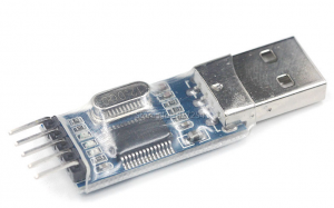
As it is now you need to restart the unit to have it detect the change but you could make it dynamic by calling dprint_init(LEVEL) regularly from you main loop.
(note to the early adopters: There was a missing ‘()’ when it was first published this is fixed now)
From now on, all my projects will contain a permanent USB-uart for the debug-stream. it is an extra cost of 50 cent, two wires and a pin. I can afford that.
Happy hacking
StorePeter peter@storepeter.dk
]]>
Jeg bestilte en Tevo Tarantula kit fra Kina som dukkede op efter 24 dage, og den spytter faktisk ganske hæderlige prints ud, specielt hvis man holder sig til PLA. Der er en del problemer, men også gode muligheder for at forbedre printeren og der er masser af youtube videoer om det. Jeg vil dog kun lave et minimum af ændringer og istedet bygge en ny.
Min printer skal bestemt være opensource og alt programmel skal køre under Linux. Indtil videre har jeg brugt.
- Marlinfw.org, compilere og installere Firmware på Tarantula vhja. Arduino-1.8.5 under Linux.
- Pronterface.com GUI printer kontrol, installering
- Cura fra Ultimaker slicing software til at genere Gcode fra .stl filer
- Slic3r fra Prusa slicing software til at genere Gcode fra .stl filer
- OctoPi – Octoprint on Raspberry Pi – WEB baseret access/monitoring af 3D-printer.
Hvilken type skal jeg så bygge ? Der er masser af RepRap_Options
- Prusa-i3 type – stepper motorer til X Y Z -aksen, printer-objektet flyttes i Y-aksen, X og Y aksen bliver flyttet med bælter og Z-aksen med en gevind skrue. Det ser ud til at det er favorit designet til billige og gode printere. Den jeg har købt bruger samme kinematik.
- Hangprinter et frisk pust fra Sverige, sådan en bør man næsten have
- CoreXY – En del aktivitet i selvbyg printere, let og dermed hurtig kinematik.
- Ultimaker type – Ulticampy – ikke meget aktivitet
- RepRap-Morgan Morgan – ikke meget aktivitet
- Mit eget selv-opfundne design – indtil videre ligger det trygt i hoved, og jeg har ikke set andre bruge designet – måske er det fordi det ikke er særlig godt/nemt/præcist/billigt/hurtigt – Jeg er overbevist om at det er et rigtig godt/nemt/præcist/billigt/hurtigt design men det kræver jo at jeg laver det hele selv.
- Jeg har faktisk 2 designs i mit hoved, en radian og en linear version.
Det smarteste er jo at vælge et gennemprøvet design, hvor andre har fundet og udbedret fejlene, eller i det mindste et design hvor der sker udvikling og der er folk man kan diskutere hvorfor ens printer ikke virker som forventet.
Printeren jeg vil bygge skal være en CoreXY, og der er en del versioner som folk bygger lige for tiden, og masser af inspiration og opskrifter på Youtube og Thingiverse
- HyperCube by Tech2C
- HyperCube Evolution by Scott3D, video beskriver forskel fra Tech2C
- Arturs lab building both of the above printers 21 youtube videos
- S.T.E.V.E med direct drive extrussion 19 youtube videoer
- Overblik over HyperCube resourcer: github.com/superjamie/lazyweb/wiki/3D-Printing-HyperCube
- unrelated to the above axelsdiy.brinkeby.se
Jeg kan specielt godt lide Arturs tilgang til projektet. og jeg kan fint forestille mig at ende op med en lille familie 3D-printere optimeret til hver sit materiale.
- ABS / PETG filament, lukket og opvarmet boks 200mm x 200mm x 200mm print-volume
- PLA filament, lidt større, måske 400x300x300
- PLA/flex filament, lidt mindre, bygget af delene fra min Tevo Tarantula
Efterhånden har jeg fået samlet stumper nok sammen til at bygge min egen 3D-printer, jeg er begyndt at printe delene.
Mere om det næste gang
]]>